A power battery pack

A power battery pack, rotating shaft technology, applied in battery pack components, circuits, electrical components, etc., can solve problems such as reducing product quality, BMU failure, affecting production efficiency, and ensuring normal work.

Active Publication Date: 2022-07-19
江苏和中普方新能源科技有限公司
View PDF9 Cites 0 Cited by
  • Summary
  • Abstract
  • Description
  • Claims
  • Application Information

AI Technical Summary

Problems solved by technology

Power battery pack is one of the core components of new energy vehicles, and its quality is the most important factor that determines a company's foothold in the market. At present, in the process of battery pack design, the BMU (battery management unit) is usually installed horizontally at the bottom of the box, with bolts Fixed, the wire insertion hole on the BMU is on one side. During the process of inserting wires into the wire insertion hole, due to the limited space, the operator's sight will be blocked by other parts on the box, resulting in misalignment. Pins, which often cause damage to the pins, cause BMU failures, affect production efficiency, and reduce product quality

Method used


Image

  • A power battery pack
  • A power battery pack
  • A power battery pack

Examples


Embodiment Construction

[0027] The principles and features of the present invention will be described below with reference to the accompanying drawings. The examples are only used to explain the present invention, but not to limit the scope of the present invention.

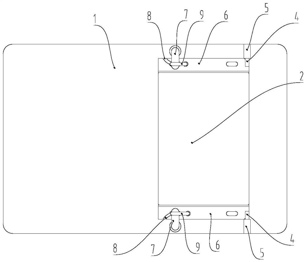
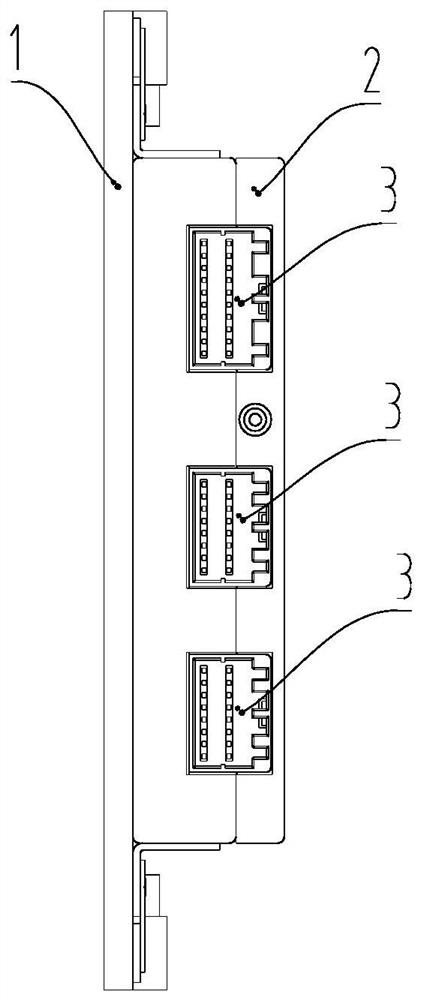
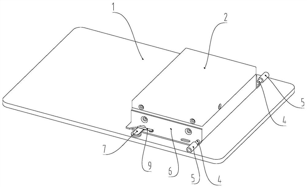
[0028] like Figure 1 to Figure 5 shown, figure 1 A schematic structural diagram of a power battery pack provided by the present invention; figure 2 for figure 1 Left side view of power battery pack shown; image 3 for figure 1 Schematic diagram of the three-dimensional structure of the power battery pack shown; Figure 4 for figure 1 The structural schematic diagram of the tableting shown in; Figure 5 for figure 1 Schematic diagram of the structure of the elastic sheet shown in . In the drawings, for the convenience of description, the box body 1 is a simple schematic diagram, and is actually a box body structure.

[0029] In a specific embodiment of a power battery pack provided by the present invention, a power battery pac...


PUM


Abstract

The present invention provides a power battery pack, which includes a box body and a BMU installed at the bottom of the box body, one side of the BMU has a plug-in hole, and one end of the BMU away from the plug-in hole is connected to the box. The body is hinged, and one end of the BMU close to the plug-in hole is detachably connected to the box body. The BMU installation device in the power battery pack has a simple structure and is easy to operate. In the process of operating the BMU plug-in, it can ensure that the plug and the BMU connector are installed vertically, so as to avoid damage to the pins and improve product quality.

Description

technical field [0001] The invention relates to the field of electric vehicles, in particular to a power battery pack. Background technique [0002] my country is currently in the period of energy conversion of vehicles, and new energy vehicles are increasing day by day. In major enterprises, the safety of new energy vehicles has attracted more and more attention. As one of the core components of the new energy vehicle, the power battery pack is the most important factor determining the company's foothold in the market. At present, in the battery pack design process, the BMU (battery management unit) is usually installed horizontally at the bottom of the box, with bolts. Fixed, the plug-in hole on the BMU is on one side. During the process of plugging the wire into the plug-in hole, due to the limited space, the operator's sight will be blocked by other components in the box, resulting in incorrect insertion. Pins, which often damage the pins, cause BMU failures, affect pro...

Claims


Application Information

Patent Timeline
Patent Type & Authority Patents(China)
IPC IPC(8): H01M50/258H01M50/249H01M50/296H01M50/298
CPCH01M50/20Y02E60/10
Inventor 李鸿键王小龙单长征杨振忠盛力赵孟杨槐宋春红
Owner 江苏和中普方新能源科技有限公司
Why Eureka
Try Eureka