A power network and its control system and control method, and network dispatching device

A power network and control device technology, applied in the field of electric power, can solve the problems of large power grid demand, low utilization rate of production equipment and grid-connected micro-grid, etc., and achieve the effect of reducing management difficulty

Active Publication Date: 2018-12-18
ENN SCI & TECH DEV
View PDF5 Cites 0 Cited by
  • Summary
  • Abstract
  • Description
  • Claims
  • Application Information

AI Technical Summary

Problems solved by technology

[0005] Embodiments of the present invention provide a power network and its control system and control method, and a network scheduling device, which are used to improve the problem of low utilization of production equipment in the prior art in order to meet the supply and demand balance of grid-connected microgrids or Grid-connected microgrid has a large demand on the grid

Method used


Image

  • A power network and its control system and control method, and network dispatching device
  • A power network and its control system and control method, and network dispatching device
  • A power network and its control system and control method, and network dispatching device

Examples


Embodiment 1

[0057] In the following, a power network provided by an embodiment of the present invention will be described in detail.

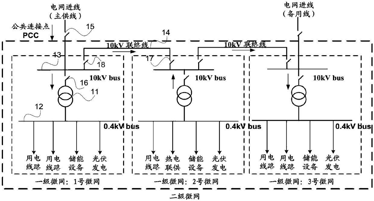
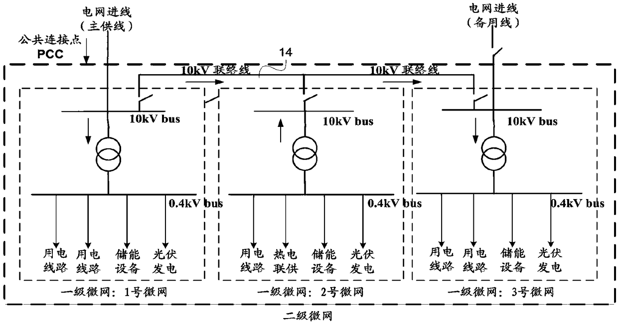
[0058] This embodiment provides a power network, which is composed of N microgrids, where N≥2. In this embodiment, N=3 is taken as an example, refer to figure 2 , the power network is a secondary microgrid composed of three first-level microgrids: No. 1 microgrid, No. 2 microgrid, and No. 3 microgrid.

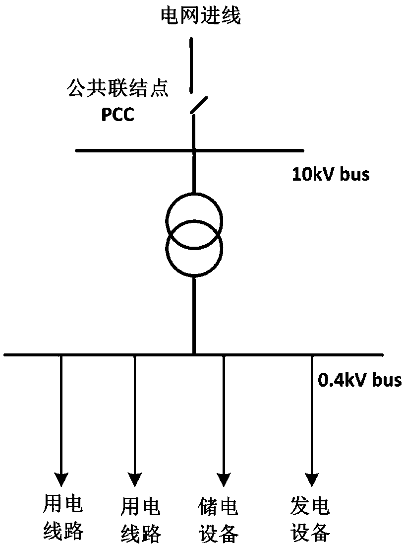
[0059] Specifically, taking No. 1 microgrid as an example, each microgrid includes: a first bus (bus) 12 and a second bus 13 connected through a transformer device 11 . The first bus 12 is connected to the low-voltage side of the transformation equipment 11, for example a 0.4kV low-voltage bus, and the second bus 13 is connected to the high-voltage side of the transformation equipment 11, for example a 10kV high-voltage bus. In the power system, the busbar connects the various current-carrying branch circuits in the power distribution device, and plays t...

Embodiment 2

[0073] In the following, a control system for a power network provided by an embodiment of the present invention will be described in detail.

[0074] The control system provided by the embodiment of the present invention includes: N micro-grid control devices, and a network scheduling device connected to the N micro-grid control devices, where N≥2.

[0075] In this embodiment, the power network composed of three microgrids is taken as an example, refer to Figure 4 , the control system of the power network includes 3 microgrid control devices, namely No. 1 microgrid control device, No. 2 microgrid control device and No. 3 microgrid control device; and a network dispatching device connected to the 3 microgrid control devices . Wherein, each micro-grid control device is used to complete the internal management of the micro-grid it controls, and is controlled by the network scheduling device of the secondary micro-grid. As the management system of the second-level microgrid, t...

Embodiment 3

[0113] An embodiment of the present invention provides a control method of a power network, the power network is the power network described in Embodiment 1, and the specific operation steps of the control method are as follows Figure 10 shown, including:

[0114] S101. The network scheduling device receives microgrid information and connection line information sent by each microgrid control device.

[0115] The micro-grid information received by the network scheduling device includes: capacity equipment information, transmission equipment information, and load information. The tie line information received by the network dispatching device specifically refers to tie line switch status information, current / power information on the tie line, and the like. For specific reference to Embodiment 2, details are not repeated here.

[0116] For example, refer to Figure 5 , the micro-grid information and tie-line information received by the network scheduling device include: the p...


PUM


Abstract

The embodiment of the present invention discloses a power network and its control system, control method, and network scheduling device, which relate to the field of electric power and are used to improve the utilization rate of production capacity equipment in the prior art in order to meet the supply and demand balance of grid-connected micro-grids The problem of low energy consumption or the problem of large demand on the grid for grid-connected microgrids. The method includes: N microgrids, N≥2; each microgrid includes: transformer equipment, a first busbar, a second busbar, production equipment and loads, and a tie line. A tie line switch is set on the tie line, and the tie line switch is used to control the connection or disconnection of the connected microgrids; N microgrids are divided into M microgrid groups, and the microgrids in each group are connected through tie lines, and each microgrid At least one microgrid in the network group is connected to the grid power supply line through the access switch at the common connection point PCC, and only one access switch in each group is connected to the grid power supply line, 1≤M≤N.

Description

technical field [0001] The invention relates to the field of electric power, in particular to an electric power network, its control system and control method, and a network dispatching device. Background technique [0002] Due to its high efficiency, cleanliness, and flexibility, distributed energy can complement traditional energy sources. Micro-grid (micro-grid), also known as micro-grid, micro-grid, is an important utilization method of distributed energy, and it is a system mainly composed of load and production equipment (mainly including distributed power generation equipment) . A microgrid can either be connected to an external grid or run in isolation. [0003] refer to figure 1 As shown, the microgrid running in parallel with the grid is a grid-connected microgrid, which is characterized by internal production equipment and loads, and the grid through a public connection point (also called a public connection point, which can be referred to as PCC: point of comm...

Claims


Application Information

Patent Timeline
Patent Type & Authority Patents(China)
IPC IPC(8): H02J3/38H02J3/32H02J3/06
CPCH02J3/06H02J3/32H02J3/38
Inventor 舒鹏王学博刘梦琼
Owner ENN SCI & TECH DEV
Why Eureka
Try Eureka