bearing ring with retaining flange

A technology of bearing rings and flanges, applied in the field of bearing rings, can solve problems such as cracks and achieve good thermal expansion effects

Active Publication Date: 2020-03-31
AB SKF
View PDF10 Cites 0 Cited by
  • Summary
  • Abstract
  • Description
  • Claims
  • Application Information

AI Technical Summary

Problems solved by technology

[0004] However, this has the disadvantage that thermal expansion of the material occurs during the induction hardening process, which is critical in the area of ​​the retaining flange, since the retaining flange and/or the shoulder of the bearing ring adjacent to the retaining flange are usually The case is not hardened and correspondingly also not heated, so that ve

Method used


Image

  • bearing ring with retaining flange
  • bearing ring with retaining flange

Examples


Embodiment Construction

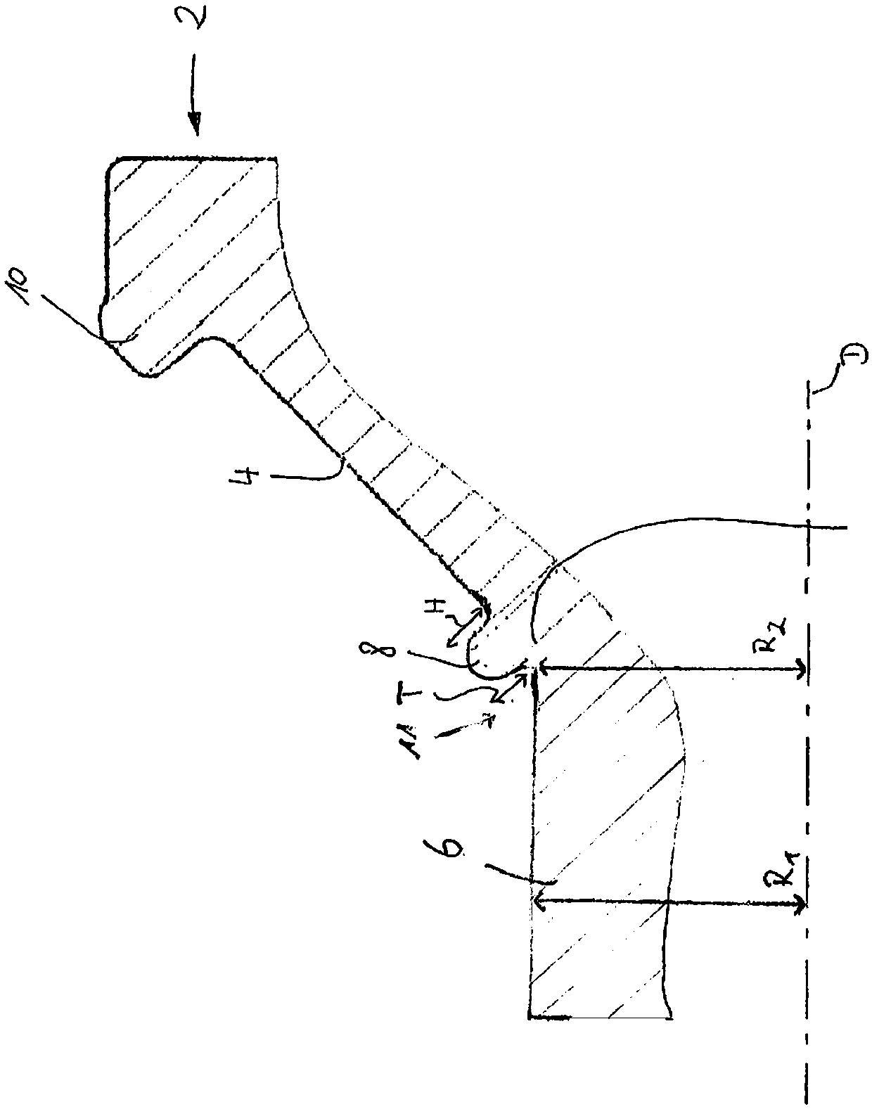
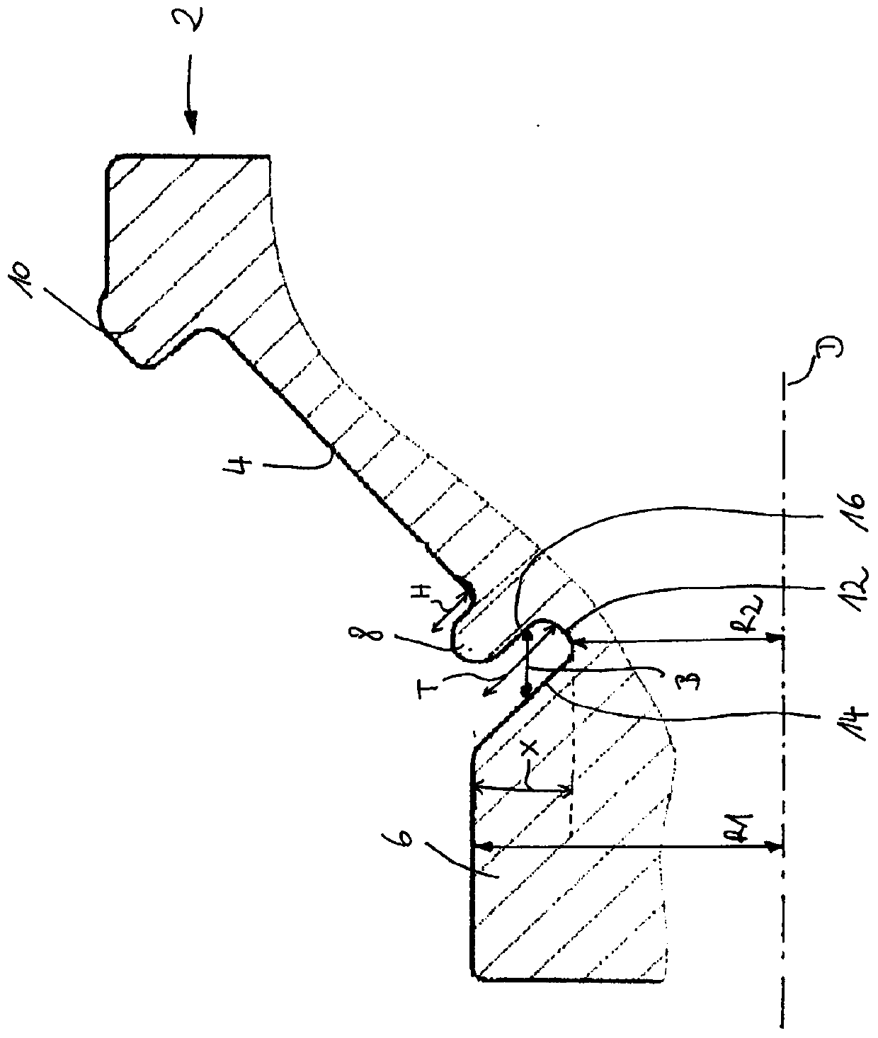
[0040] figure 1 A schematic cross-sectional view of a bearing ring 2 according to the invention is shown, which has a raceway surface 4 on which rolling elements (not shown) can be arranged. Furthermore, the bearing ring 2 has a guide flange 10 and a retaining flange 8 transitioning into the bearing ring shoulder 6 , wherein in particular the retaining flange 8 is higher than the raceway surface 4 of the bearing ring 2 by a height H. Here, the bearing ring shoulder 6 and the retaining flange 8 are the edge regions of the bearing ring 2 which do not need to be hardened, while the raceway surface 4 and the guide flange 10 are preferably induction hardened.

[0041] like figure 1 It is further shown that the retaining flange 8 is configured to be free-standing and has an open space 11 between the shoulder 6 and the retaining flange 8, which is preferably configured here as a groove 12, which is constructed as complete The groove has a depth T and a width B. Wherein, the de...


PUM


Abstract

The invention discloses a bearing ring (2) of a rolling bearing, said bearing ring having a raceway surface (4) for rolling elements and at least one flange (8) transitioning to a shoulder (6) of the bearing ring, Said flange protrudes beyond the raceway surface (4) by a height (H), wherein an open space (11) is formed between the bearing ring shoulder (6) and the flange (8), so that the flange (8) is Constructed to be independent over its entire height (H); and a rolling bearing with such a bearing ring (2) is also disclosed.

Description

technical field [0001] The invention relates to a bearing ring and a rolling bearing with such a bearing ring Background technique [0002] In general, the bearing inner ring and the bearing outer ring of rolling bearings respectively have raceway surfaces for arranging the rolling elements. Furthermore, the bearing ring can have radially arranged flanges (bords), so-called retaining flanges (Haltebord) and / or guide flanges (Führungsbord), wherein the retaining flanges are used during mounting of the bearing and / or during transport. for supporting the rolling elements, while the guide flange (especially during bearing operation) acts as an axial rolling element guide. Thus, the holding flange and / or guide flange is arranged axially close to the raceway surface of the bearing ring and limits the axial extension of the raceway surface. For cylindrical roller bearings, the rolling elements are configured as cylindrical rolling elements, and for tapered roller bearings, the...

Claims


Application Information

Patent Timeline
IPC IPC(8): F16C33/58
CPCF16C33/583F16C2223/10F16C19/364F16C19/386F16C33/64F16C2223/18F16C33/585F16C33/605
Inventor 玛蒂娜·施蒂希特格哈德·瓦格纳
Owner AB SKF
Why Eureka
Try Eureka