

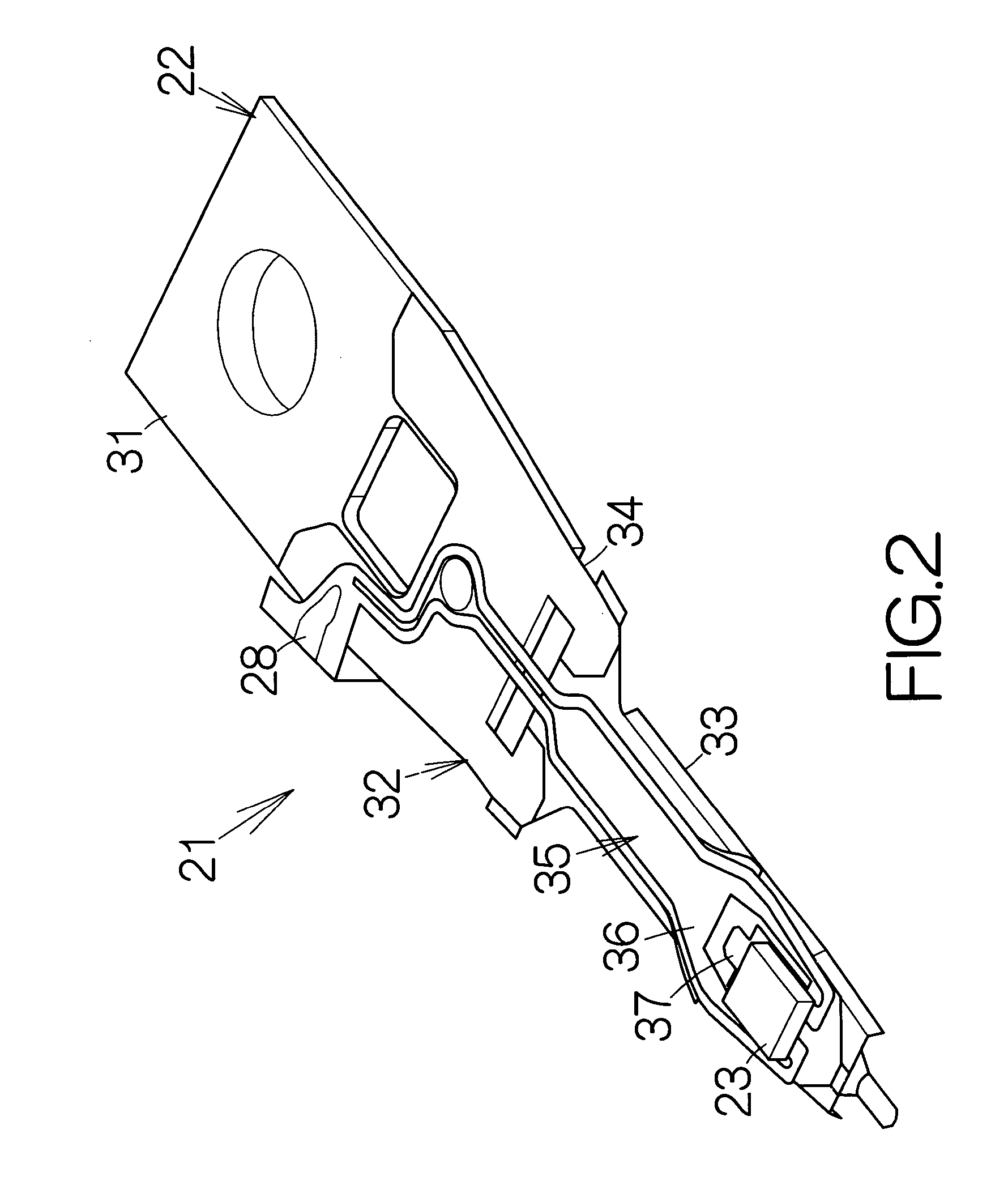
Head suspension assembly contributing to constant flying height of head slider
a technology of suspension assembly and slider, which is applied in the direction of maintaining the alignment of the head carrier, recording information storage, instruments, etc., can solve the problems of flying slider deformation, and achieve the effect of preventing the deformation of the slider and effectively contributing to establishmen
- Summary
- Abstract
- Description
- Claims
- Application Information
AI Technical Summary
Benefits of technology
Problems solved by technology
Method used
Image

Examples
Embodiment Construction
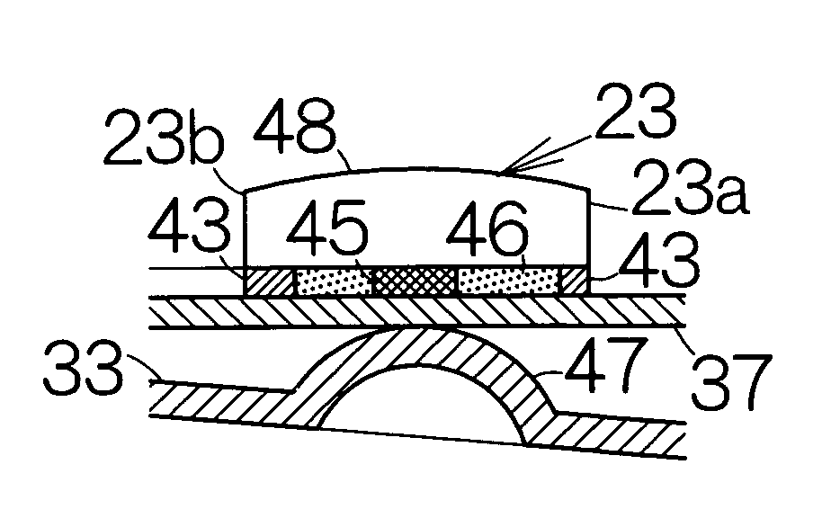
[0028]FIG. 1 schematically illustrates the inner structure of a hard disk drive, HDD, 11 as an example of a recording medium drive or storage device. The hard disk drive 11 includes a box-shaped enclosure 12. The enclosure 12 includes a boxed-shaped base 13 defining an inner space of a flat parallelepiped, for example. The base 13 may be made of a metallic material such as aluminum, for example. Molding process may be employed to form the base 13. A cover, not shown, is coupled to the base 13. The cover closes the opening of the inner space with in the base 13. Pressing process may be employed to form the cover out of a plate material, for example.
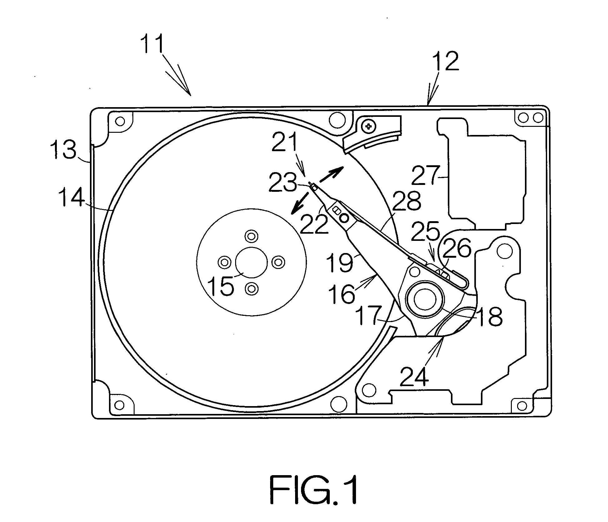
[0029] A printed circuit board, not shown, is fixed on the outside of the base 13. LSI chips, connectors, and the like, are mounted on the printed circuit board. The LSI chips may include a controller or central processing unit, CPU, a hard disk controller, HDC, and the like. The central processing unit and the hard disk controller serve ...
PUM
 Abstract
Description
Claims
Application Information