

Intelligent pan with temperature measuring function
A technology of temperature measurement function and cooking utensils, which is applied to the structure of household utensils, kitchen utensils, cooking utensils, etc., can solve the problems of unreasonable setting of temperature measurement points, complicated manufacturing process, and easy failure of detection points, etc., to achieve safe use, The effect of uniform distribution and large temperature measurement range
- Summary
- Abstract
- Description
- Claims
- Application Information
AI Technical Summary
Problems solved by technology
Method used
Image


Examples
specific Embodiment 1
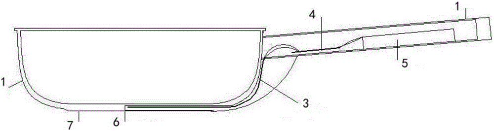
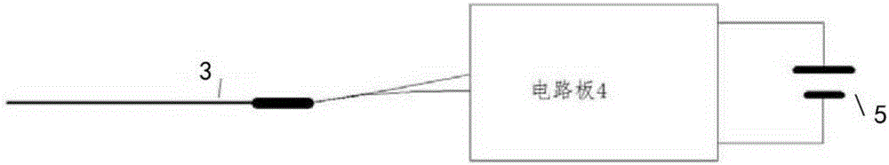
[0027] refer to Figure 1-Figure 3 , present embodiment 1 comprises pot body 1 and handle 2, is provided with attached bottom 7 on the bottom surface of pot body 1, is provided with thermocouple 3 at the junction of pot body 1 and attached bottom 7, and the detecting end of described thermocouple 3 Hidden near the central position of the bottom surface of the pot body 1 and in contact with the bottom surface of the pot body 1, a temperature measuring structure for directly detecting the central position of the pot body and its surroundings is formed; a circuit board 4 and a battery 5 are arranged in the handle 2, and a There is a signal acquisition and processing circuit and a wireless signal output circuit, the signal output end of the thermocouple 3 is connected to the signal input end of the signal acquisition and processing circuit, the output end of the signal acquisition and processing circuit is connected to the input end of the wireless signal output circuit, and the wi...
specific Embodiment 2
[0034] see Figure 4 , the characteristics of the specific embodiment 2 of the present invention are: the pot body 1 is a round bottom pot, and the bottom of the pot is an arc surface or a round bottom. 7 is closely combined with the pot body 1, and the hot end of the thermocouple 3 is inserted into the capillary steel pipe 6, extending straight to the inside of the bottom of the pot. The installation range of the thermocouple 3: taking the center of the pot as the center point, is about 2 / 3 of the surface area of the whole pot. All the other are with specific embodiment 1.
specific Embodiment 3
[0036] see Figure 5 , The characteristics of the specific embodiment 3 of the present invention are: the pot body 1 is a flat-bottomed pressure cooker. All the other are with specific embodiment 1.
[0037] In order to overcome the above disadvantages, the present invention needs to design an intelligent pot that can adapt to the temperature change of the bottom of the pot, has a large measurement range, small error, simple process, and is safe to use.
PUM
| Property | Measurement | Unit |
|---|---|---|
| Thickness | aaaaa | aaaaa |
| Thickness | aaaaa | aaaaa |
| Diameter | aaaaa | aaaaa |
Abstract
Description
Claims
Application Information