Steel tube cutting machine

A cutting machine and cutting mechanism technology, which can be applied to pipe shearing devices, shearing devices, accessories of shearing machines, etc., can solve problems such as blade damage, complex structure, and increased product production costs.

Active Publication Date: 2017-01-04
ZHEJIANG AOTAI MACHINE MFG
View PDF7 Cites 2 Cited by
  • Summary
  • Abstract
  • Description
  • Claims
  • Application Information

AI Technical Summary

Problems solved by technology

[0002] The cutting and feeding of the existing steel pipe cutting machine are independent, so the structure is relatively complicated, and the production cost of the product is also greatly increased
In addition, the steel pipe cutting machine needs to have a good positioning of the s

Method used


Image

  • Steel tube cutting machine
  • Steel tube cutting machine
  • Steel tube cutting machine

Examples


Embodiment Construction

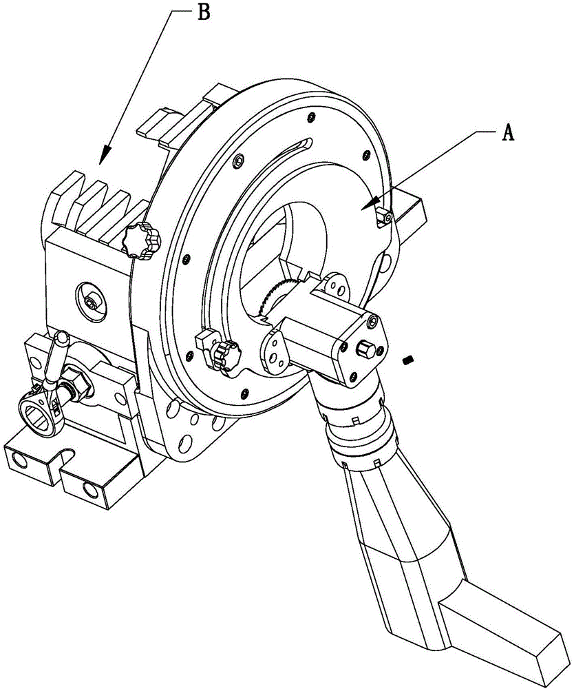
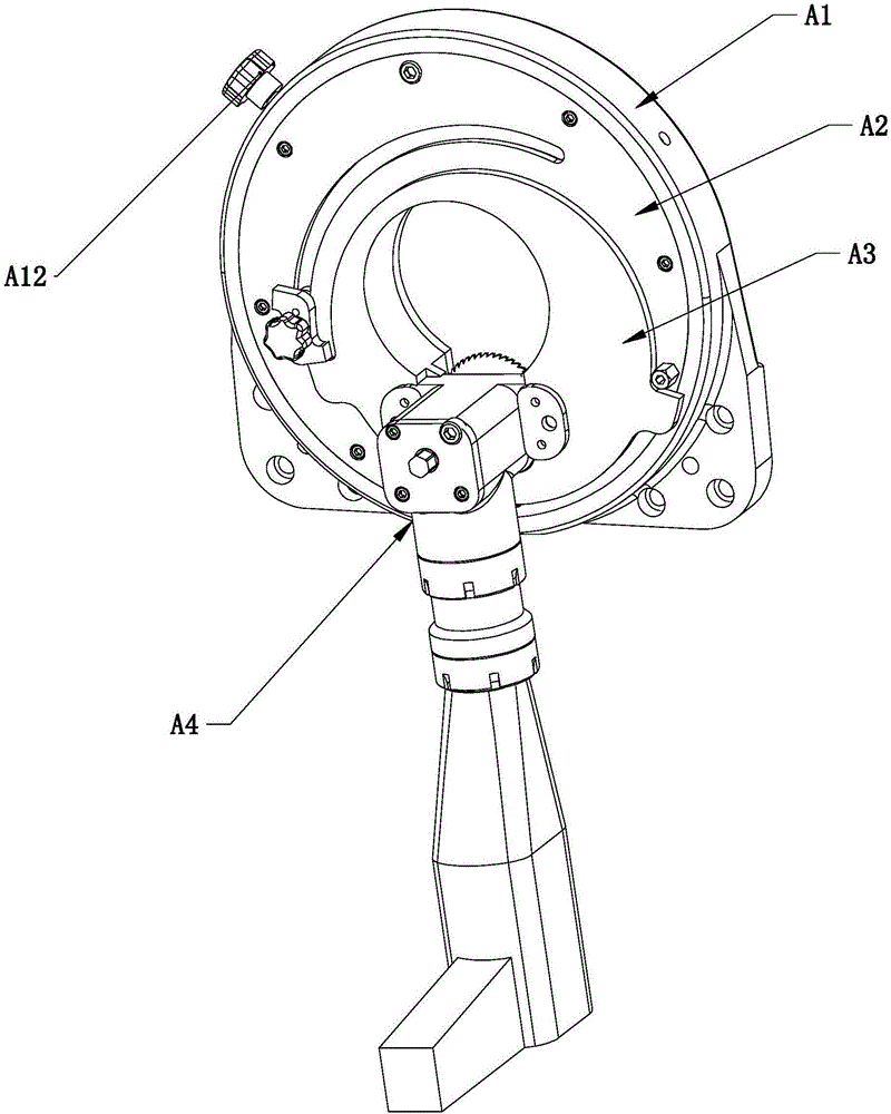
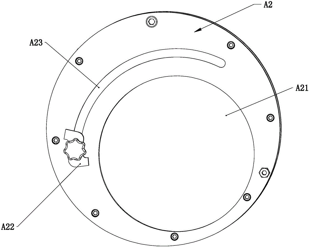
[0025] Such as figure 1 — Figure 13 As shown, a steel pipe cutting machine includes a cutting mechanism A and a clamping mechanism B. The cutting mechanism A includes a bracket A1, a rotating disk A2, a feed control rotating disk A3 and a blade cutting device A4. Here we will explain The blade cutting device A4 is a device that drives the blade to rotate through a motor. It is also common in the general market. Its main function is to realize the function of blade rotation. It is circular, and the rotating disk A2 is rotated and installed on the circular through hole A11 of the bracket A1. The rotating disk A2 is eccentrically provided with a circular through hole A21, and the feed control dial A3 is rotated and installed on the circular through hole A21. Among them, a cutting through hole A31 is provided at an eccentric position on the feed control turntable A3, and the blade cutting device A4 is fixedly arranged on the feed control turntable A3, and the blade cutting devic...


PUM


Abstract

The invention relates to a steel tube cutting machine and particularly relates to a cutting mechanism on a steel tube cutting machine. The technical scheme of the invention is as follows: the cutting mechanism of the steel tube cutting machine is characterized by comprising a bracket, a rotating disc, a feed control rotating disc and a blade cutting device, wherein a round through hole is formed in the bracket; the rotating disc is rotatably arranged on the round through hole of the bracket; a mounting round through hole is eccentrically formed in the rotating disc; a cutting through hole is formed in the eccentric position of the feed control rotating disc; a baffle block is arranged on the feed control rotating disc; a limiting block matched with the baffle block to limit rotation of the feed control rotating disc is arranged on the rotating disc; and after the feed control rotating disc rotates at a set angle, the baffle block leans against the limiting block to drive the rotating disc to rotate together. By adopting the technical scheme, the invention provides the novel cutting mechanism of the steel tube cutting machine, wherein the cutting mechanism conveniently machines and is convenient to adjust feed.

Description

technical field [0001] The invention relates to a cutting machine, in particular to a steel pipe cutting machine. Background technique [0002] Existing steel pipe cutting machine's cutting and feeding are all independent, so the structure is relatively complicated, and the production cost of the product is also greatly increased in addition. In addition, the steel pipe cutting machine needs to have a good positioning of the steel pipe, and it must be suitable for clamping different steel pipes. The requirements for the clamping mechanism of the steel pipe cutting machine are particularly high. Once the clamping is unstable, the blade will be damaged. Now Some steel pipe cutting machines have this problem. Contents of the invention [0003] The invention overcomes the deficiencies in the prior art and provides a novel steel pipe cutting machine with convenient processing and convenient adjustment of feed. [0004] In order to achieve the above object, the present inventi...

Claims


Application Information

Patent Timeline
IPC IPC(8): B23D21/00B23D33/02
CPCB23D21/00B23D33/02
Inventor 项光春项玉振张海峰张洪华
Owner ZHEJIANG AOTAI MACHINE MFG
Why Eureka
Try Eureka