Auxiliary jig for polishing of side of light guide plate

A light guide plate and jig technology, which is applied to surface polishing machine tools, grinding/polishing equipment, manufacturing tools, etc., can solve problems affecting the quality of the light guide plate, poor safety, deformation of the side of the light guide plate, etc., and achieve convenient manual polishing The effect of improving the operation, improving safety, and improving the strength against deformation

Active Publication Date: 2017-01-04
东莞新涛有机玻璃有限公司
View PDF6 Cites 2 Cited by
  • Summary
  • Abstract
  • Description
  • Claims
  • Application Information

AI Technical Summary

Problems solved by technology

After the light guide plate is processed, it generally needs to be polished. The common polishing is generally the front and back of the light guide plate. However, after the light guide plate is cut and cut, the side of the light guide plate also needs to be polished. Manual polishing, that is, holding the light guide plate to work on the polishing disc, but its safety is poor. At the same time, because the thickness of the light guide plate itself is thin, hand-held polishing is easy to cause deformation of the side of the light guide plate, which affects the quality of the light guide plate

Method used


Image

  • Auxiliary jig for polishing of side of light guide plate
  • Auxiliary jig for polishing of side of light guide plate
  • Auxiliary jig for polishing of side of light guide plate

Examples


Embodiment Construction

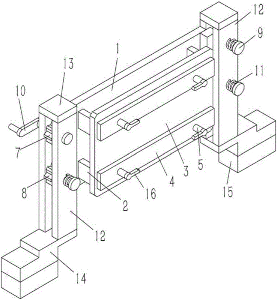
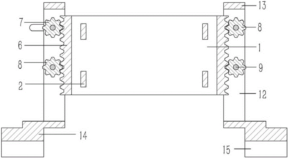
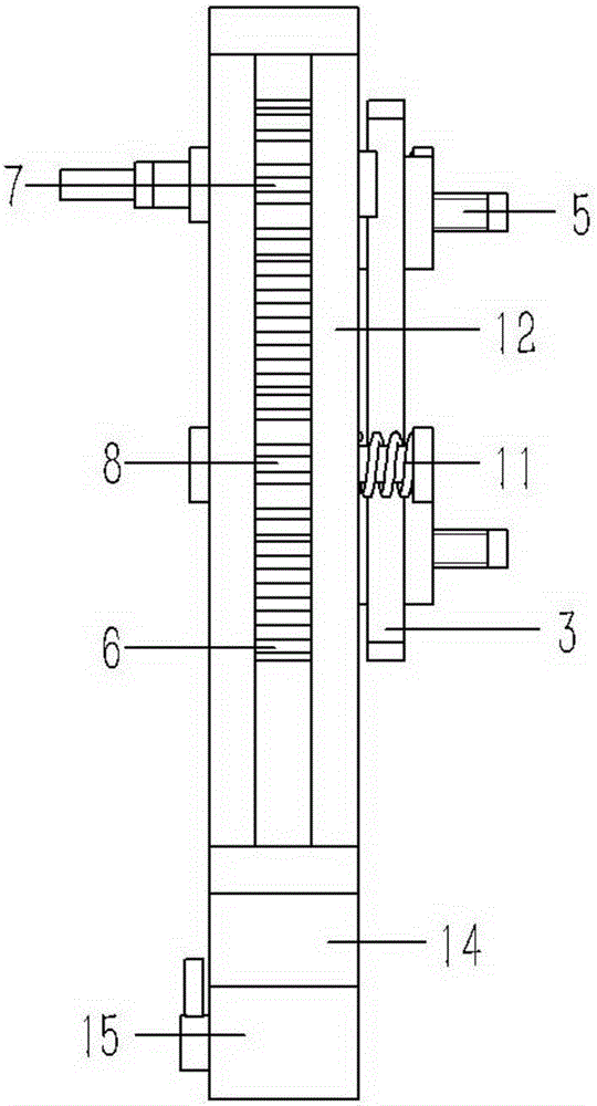
[0022] Example: see Figures 1 to 3 As shown, an auxiliary jig for polishing the side of the light guide plate, including a rear splint 1, a number of inserting plates 2 are fixed on both sides of the front end of the rear splint 1, and the front ends of the inserting plates 2 pass through the front splint 3 and are fixed on the positioning plate 4 , the positioning plate 4 is screwed with some fastening bolts 5; vertical racks 6 are fixed on both sides of the rear splint 1, and the rack 6 on one side of the rear splint 1 is engaged with a driving gear 7 and a driven gear respectively. Gear 8, the driven gear 8 is meshed with the rack 6 on the other side of the rear splint 1, the driven gear 8 or the driving gear 7 are inserted and fixed on the hinge shaft 9, and the two ends of the hinge shaft 9 are respectively hinged on the side plate 12 Above, the upper end of the side plate 12 is fixed on the connection block 13, the lower end of the side plate 12 is fixed on the connecti...


PUM


Abstract

The invention discloses an auxiliary jig for polishing of side of a light guide plate. The jig comprises a rear clamping plate, a plurality of insertion plates are fixed to the two sides of the front end face of the rear clamping plate, the front ends of the insertion plates penetrate through a front clamping plate to be fixed to a positioning plate, and a plurality of fastening bolts are connected with the positioning plate through threads; the two side edges of the rear clamping plates are fixedly provided with vertical racks, the rack on one side of the rear clamping plate is meshed with a driving gear and a driven gear, the rack on the other side of the rear clamping plate is meshed with a driven gear, the driven gears and the driving gear are fixed to hinge shafts in an inserted and sleeved mode, the two ends of each hinge shaft are hinged to side plates respectively, the upper ends of the side plates are fixed to connection blocks, the lower ends of the side plates are fixed to connection bases, and the bottom ends of the connection bases are fixedly connected with magnet suction cups; one end of the portion, on the driving gear, of the corresponding hinge shaft is fixedly connected with a rocker. The jig is simple in structure, assists a manual polishing light guide plate in use, brings convenience to manual polishing, and can effectively improve polishing safety.

Description

[0001] Technical field: [0002] The invention relates to the technical field of light guide plate processing equipment, and more specifically relates to an auxiliary jig for polishing the side of a light guide plate. [0003] Background technique: [0004] With the development of the liquid crystal industry, the light guide plate has been widely used and has become an indispensable part of the liquid crystal module. The main function of the light guide plate is: after the LED light source is introduced from the side, it will be reflected by the printing dots in the later stage to make the light source uniform. After the light guide plate is processed, it generally needs to be polished. The common polishing is generally the front and back of the light guide plate. However, after the light guide plate is cut and cut, the side of the light guide plate also needs to be polished. Manual polishing, that is, holding the light guide plate to work on the polishing disc, but its safety...

Claims


Application Information

Patent Timeline
Patent Type & Authority Applications(China)
IPC IPC(8): B24B41/06B24B29/02
CPCB24B29/02B24B41/06
Inventor 王文庆
Owner 东莞新涛有机玻璃有限公司
Why Eureka
Try Eureka