
3D printing method based on force feedback system

A 3D printing and force feedback technology, applied in the field of 3D printing, can solve the problems of printing failure and no way to guarantee the accuracy, and achieve the effect of improving the success rate, ensuring the consistency and ensuring the printing quality.

Active Publication Date: 2017-01-04
GUANGZHOU HEYGEARS INTELLIGENT TECH CO LTD
View PDF4 Cites 6 Cited by
  • Summary
  • Abstract
  • Description
  • Claims
  • Application Information

AI Technical Summary

Problems solved by technology

[0003] However, in traditional DLP 3D printing, the contact and separation between the forming platform and the bottom of the material tray has always been a big problem
Because after each contact exposure molding, it can be said that the bottom of the material plate and the forming platform are adhered together. Next, in order to continue printing, it is inevitable that each layer must be peeled off once, that is, the bottom part of the forming platform and the material plate. Leaving aside, the traditional printing equipment does not calculate the peeling strength according to the size of the printing area, but always peels directly at a fixed speed, which often causes printing failure due to too fast separation; in the first DLP printing Before layering, the forming platform needs to be in full contact with the bottom of the material tray, that is, to find the bottom. In traditional DLP printing, the process of finding the bottom can only be completed with the cooperation of human eyes, and there is no way to guarantee the accuracy, which may lead to subsequent printing failures.

Method used


Image

  • 3D printing method based on force feedback system

Examples


Embodiment Construction

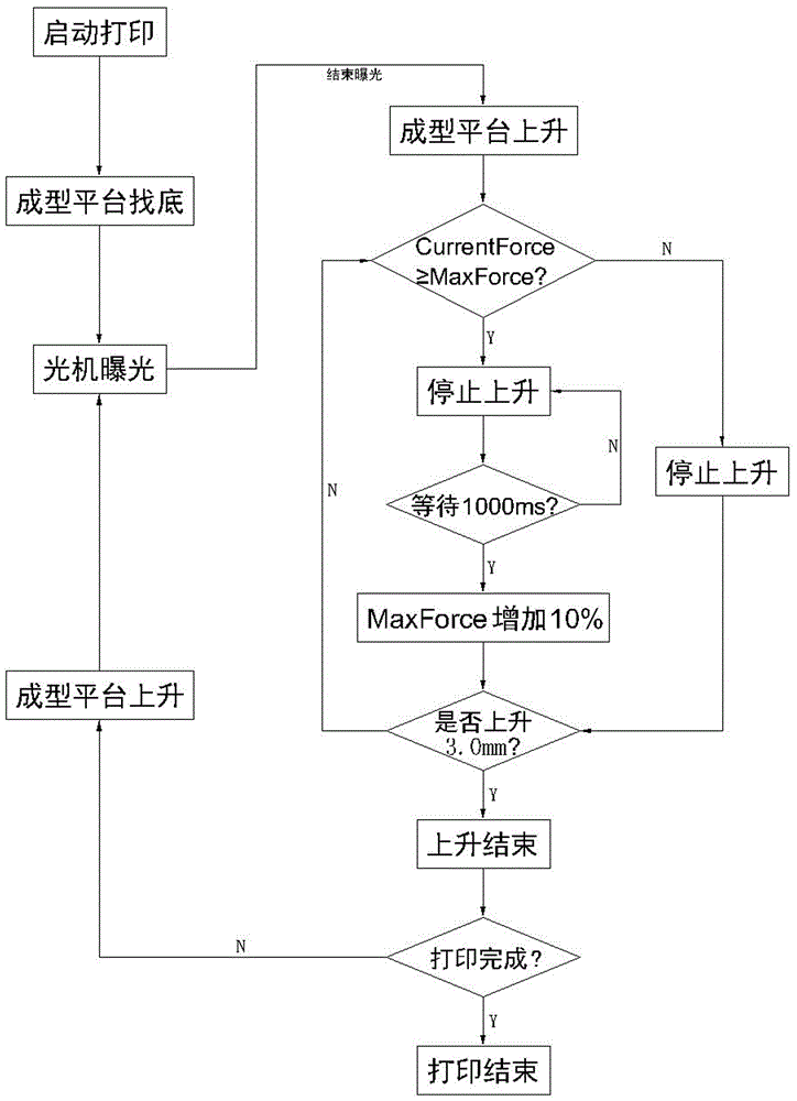
[0033] Such as figure 1 As shown, the 3D printing method based on the force feedback system in the embodiment of the present invention includes the following steps:

[0034] Step a) When printing is started, the motor drives the forming platform to start moving down, and the force feedback system collects mechanical data during the downward movement of the forming platform. When the collected data reaches 20N (the pressure value at which the forming platform is in full contact with the material disk), The motor stops, and the forming platform successfully finds the bottom;

[0035] Step b) After the bottom is found successfully, the light machine starts to expose, and the first layer of photocuring printing is carried out;

[0036] Step c) After the exposure is over, the motor drives the forming platform to move up for peeling, and the force feedback system collects the current peeling force CurrentForce in the peeling process in real time, and compares it with the threshold ...


PUM


Abstract

The invention discloses a 3D printing method based on a force feedback system. The method includes the following steps that firstly, when printing is started, a motor drives a forming platform to begin to move downwards, and the force feedback system controls the forming platform to successfully find the bottom; secondly, exposure printing of a first layer is carried out; thirdly, after exposure is finished, the forming platform moves upwards for stripping, and meanwhile the current stripping force CurrentForce is compared with a threshold value MaxForce set in the current state of the force feedback system; fourthly, if CurrentForce>=MaxForce, the forming platform stops moving upwards or moves upwards in a decelerating mode, and the fifth step is executed, and if CurrentForce<MaxForce, the forming platform continues moving upwards, and the sixth step is executed; fifthly, MaxForce is automatically increased by a scale value, and the fourth step is executed again; sixthly, the forming platform stops when moving upwards to a set height distance, and stripping is completed; seventhly, the motor drives the forming platform to move downwards again for exposure printing of a next layer; eighthly, the third step to the seventh step are repeated till printing of a printout is completed. By means of the force feedback system, the printing process is more intelligent, and the printing success rate and the printout quality are greatly improved.

Description

technical field [0001] The invention relates to the field of 3D printing, in particular to a 3D printing method based on a force feedback system. Background technique [0002] The working principle of 3D printers is basically the same as that of ordinary printers. It is to superimpose layers of "printing materials" through computer control, and finally turn the model on the computer into a real object. This is a technological revolution that subverts traditional manufacturing processes. [0003] However, in traditional DLP 3D printing, the contact and separation between the forming platform and the bottom of the material tray has always been a big problem. Because after each contact exposure molding, it can be said that the bottom of the material plate and the forming platform are adhered together. Next, in order to continue printing, it is inevitable that each layer must be peeled off once, that is, the bottom part of the forming platform and the material plate. Leaving as...

Claims


Application Information

Patent Timeline
IPC IPC(8): B29C67/00B33Y10/00B33Y50/02
CPCB33Y10/00B33Y50/02
Inventor 黄鹤源许桂鑫
Owner GUANGZHOU HEYGEARS INTELLIGENT TECH CO LTD
Learn More