Lifting mechanism which is used for stamping equipment and is provided with position adjustment function

A lifting mechanism and stamping equipment technology, applied in the direction of stamping machines, presses, manufacturing tools, etc., to achieve the effect of stable transmission and easy control

Inactive Publication Date: 2017-01-04
李振亚
View PDF0 Cites 0 Cited by
  • Summary
  • Abstract
  • Description
  • Claims
  • Application Information

AI Technical Summary

Problems solved by technology

In the prior art, the lifting mechanism with position adjustment function of stamping equipment needs to be improved

Method used


Image

  • Lifting mechanism which is used for stamping equipment and is provided with position adjustment function

Examples


Embodiment Construction

[0010] It should be understood that the specific embodiments described here are only used to explain the present invention, not to limit the present invention.

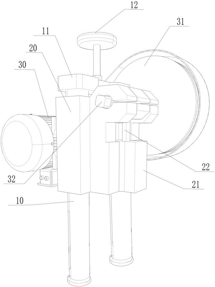
[0011] refer to figure 1 , an embodiment of the lifting mechanism with position adjustment function of the stamping equipment of the present invention is proposed:

[0012] A lifting mechanism with a positioning function for stamping equipment, comprising a mounting frame composed of two supporting columns 10 arranged at intervals and an upper fixing plate 11 transversely connected to the upper ends of the two supporting columns 10, connected to the two supporting columns 10 and positioned at The slide block base 20 below the upper fixed plate 11, the slide block 21 that is slidably connected on the slide block base 20, the drive motor 30 installed on the support column 10 rear, the reduction wheel 31 connected with the drive motor 30 by a belt, and the The crankshaft 32 to which the reduction wheel 31 is axially con...


PUM


Abstract

The invention discloses a lifting mechanism which is used for stamping equipment and is provided with a position adjustment function. The lifting mechanism comprises an assembly rack, a sliding block base which is connected onto two supporting posts and is located below an upper fixed plate, a sliding block which is slidably connected onto the sliding block base, a driving motor, a speed-reduction wheel which is connected with the driving motor through a belt and a crank which is connected with the axis of the speed-reduction wheel, wherein a rotary position adjustment screw is positioned and arranged on the upper fixed plate; the rod part of the position adjustment screw penetrates through the upper fixed plate and is connected with the sliding block base through threads; and the position adjustment screw rotates and can drive the sliding block base to slide vertically on the supporting posts, so that the vertical position of the sliding block base is adjusted. According to the lifting mechanism, the speed-reduction wheel is driven to rotate through the motor; the crank is driven to rotate by the speed-reduction wheel; the sliding block is driven to linearly and vertically move on the rail of the sliding block base through the crank; driving is more stable; and the motor is easier to control.

Description

technical field [0001] The invention relates to the field of stamping equipment, in particular to a lifting mechanism with a positioning function of the stamping equipment. Background technique [0002] Stamping equipment is a device used to stamp products. The stamping head is driven from top to bottom by the transmission mechanism. In the prior art, the lifting mechanism with position adjustment function of stamping equipment needs to be improved. Contents of the invention [0003] The main purpose of the present invention is to provide a lifting mechanism with position adjustment function of stamping equipment, aiming at realizing more stable operation of the transmission mechanism and easier control. [0004] The present invention proposes a lifting mechanism with positioning function for stamping equipment, which includes a mounting frame composed of two supporting columns arranged at intervals and an upper fixing plate transversely connected to the upper ends of the...

Claims


Application Information

Patent Timeline
IPC IPC(8): B30B1/26B30B15/00
CPCB30B1/26B30B15/0035
Inventor 李振亚
Owner 李振亚
Why Eureka
Try Eureka