
A smart card positioning device

A positioning device and smart card technology, which is applied in the direction of transportation and packaging, conveyor objects, conveyors, etc., can solve the problems of easy deviation, card offset, and large card position deviation, so as to ensure normal production and processing and simple structure , the effect of accurate positioning

Active Publication Date: 2019-06-25
SHENZHEN CHENGTIAN WEIYE TECH
View PDF9 Cites 0 Cited by
  • Summary
  • Abstract
  • Description
  • Claims
  • Application Information

AI Technical Summary

Problems solved by technology

However, during the process of transferring the card by the mechanical arm, there is likely to be a deviation between the actual position of the card at the card issuing end and the target position. The reason is that there may be a deviation between the position where the smart card reaches the When the set ideal trajectory transports the card to the card issuing end, the actual position of the card deviates from the target position; especially when the mechanical arm needs to rotate the card by 180° during the process of transporting the card, because the actual rotation center is different from the ideal The deviation of the rotation center makes the position deviation of the card larger, resulting in the inability of the card to be accurately transferred to the card issuing end, thus affecting the normal production and processing of subsequent smart cards

Method used


Image

  • A smart card positioning device
  • A smart card positioning device
  • A smart card positioning device

Examples


Embodiment 1

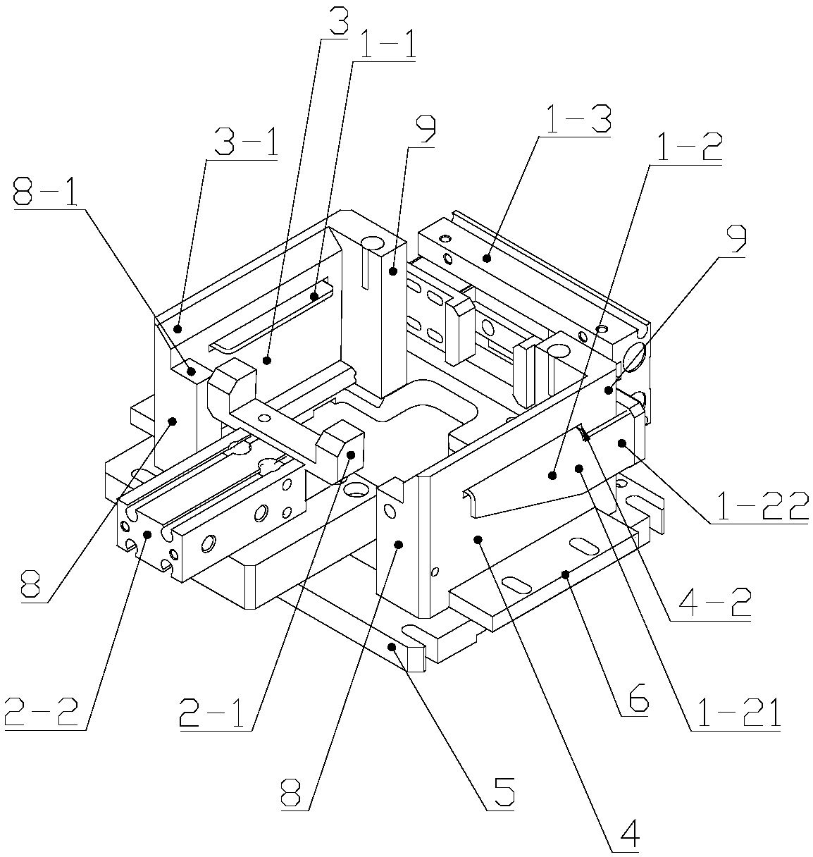
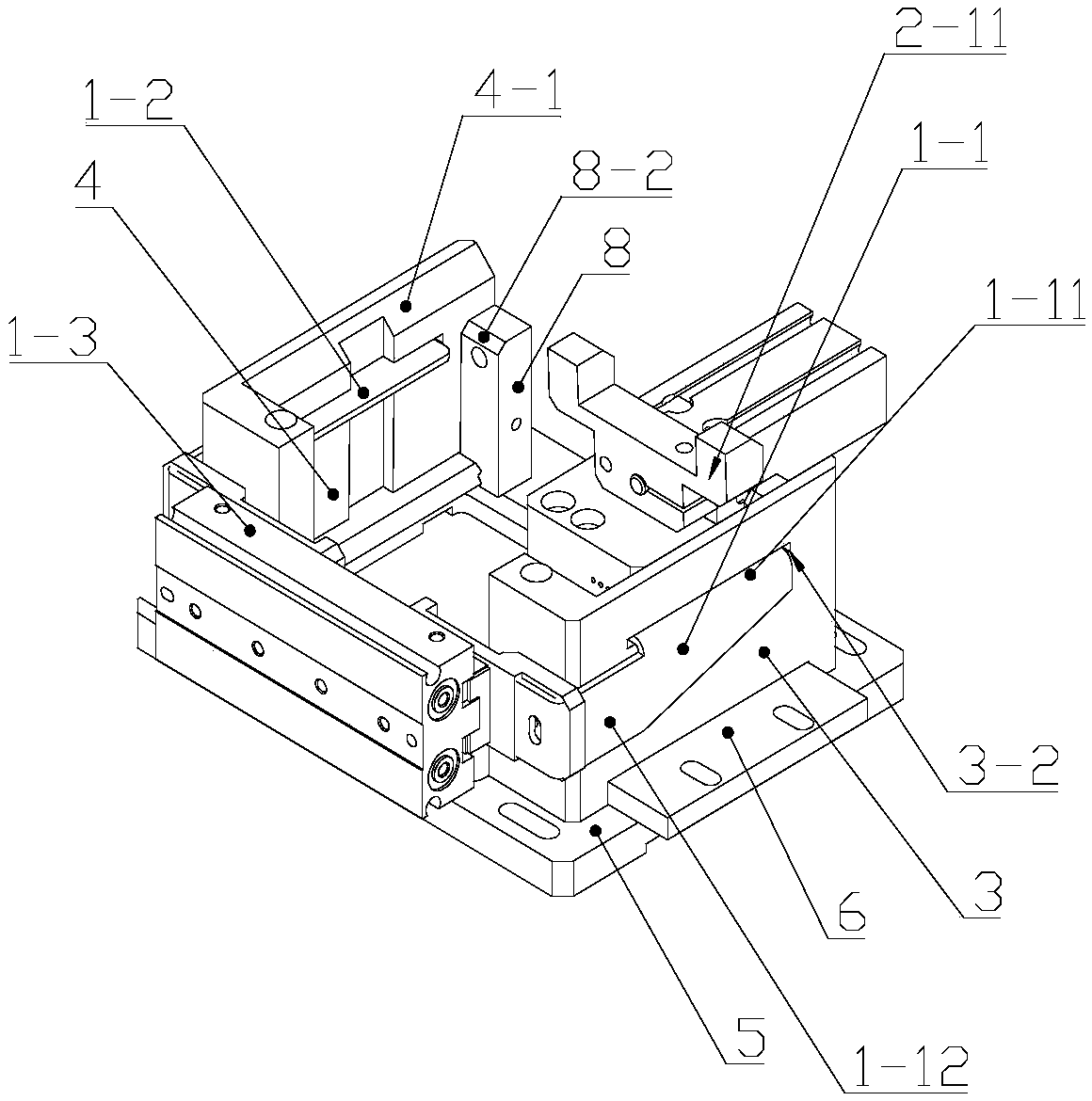
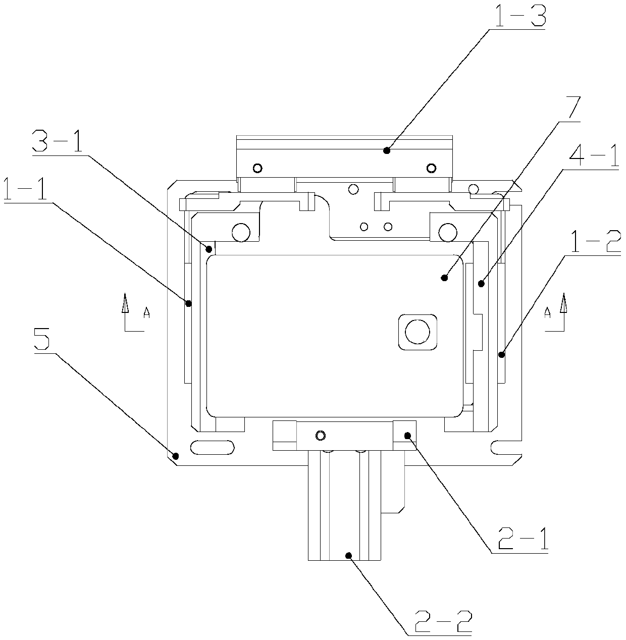
[0035] see figure 1 and figure 2, the smart card positioning device includes a positioning box, a card blocking mechanism and a card pushing mechanism; wherein, the size of the cross-section of the cavity of the positioning box matches the size of the smart card, and the positioning box includes two pairs of positioning plates opposed to each other ; wherein, the first positioning plate 3 in the first pair of positioning plates is provided with a first guide surface 3-1 and a second guide surface 4-1 on the top surface of the second positioning plate 4, the first The guide surface 3-1 and the second guide surface 4-1 are combined together to form a guide opening gradually enlarged from bottom to top; the stopper mechanism includes a first stopper 1-1, a second stopper 1-2 and a The first baffle 1-1 and the second baffle 1-2 make a first drive device 1-3 that reciprocates toward each other; a first notch 3-2 is provided below the first guide surface 3-1, so that The first ba...

Embodiment 2

[0046] The difference between this embodiment and embodiment 1 is:

[0047] see Figure 10 , the first driving device 1-3 is composed of a first cylinder 1-31 and a second cylinder 1-32; wherein, the first cylinder 1-31 drives the first baffle plate 1-1 to reciprocate, and the second cylinder drives the second gear The plate 1-2 reciprocates, and the synchronous control is used to meet the requirement for synchronization when the first baffle 1-1 and the second baffle 1-2 move.

Embodiment 3

[0049] The difference between this embodiment and embodiment 1 is:

[0050] see Figure 11 , the positioning box is made up of four positioning plates, which are respectively the first positioning plate 3 in the first pair of positioning plates, the second positioning plate 4 in the first pair of positioning plates, and the second positioning plate in the second pair of positioning plates. One positioning plate 8, the second positioning plate 9 in the second pair of positioning plates.


PUM


Abstract

The invention relates to a smart card positioning device which comprises a positioning box, a card blocking mechanism and a card pushing mechanism. The size of the cross section of an inner cavity of the positioning box is matched with that of a smart card, and the positioning box comprises two pairs of positioning plates opposite to each other, wherein the top surfaces of the first pairs of positioning plates are provided with a first guide surface and a second guide surface respectively, and the first guide surface and the second guide surface are combined together to form a guide opening which gradually expands from bottom to top; the card blocking mechanism comprises a first baffle, a second baffle and a first driving device which drives the first baffle and the second baffle do opposite reciprocating motion; the lower portion of the first guide surface is provided with a first notch, the first baffle penetrates through the first notch to enter the inner cavity of the positioning box, the lower portion of the second guide surface is provided with a second notch, and the second baffle penetrates through the second notch to enter the inner cavity of the positioning box. The positioning device is arranged in front of the card issuing end, and the transferred smart card of which the position deflects can be positioned precisely.

Description

technical field [0001] The invention relates to smart card production equipment, in particular to a smart card positioning device. Background technique [0002] In the production process of smart cards, when the smart card is sent out from the card output end of the previous production equipment and needs to be transferred to the card issuing end of the next production equipment, for example, the smart card has completed the milling slot packaging process on the slot milling packaging equipment and needs to be transferred to the personal Personalized processing equipment is used for personalization. If the distance between the card output end and the card issue end is relatively long, a mechanical arm is usually used to complete this transfer task. However, during the process of transferring the card by the mechanical arm, there is likely to be a deviation between the actual position of the card at the card issuing end and the target position. The reason is that there may be...

Claims


Application Information

Patent Timeline
Patent Type & Authority Patents(China)
IPC IPC(8): B65G47/91B65G47/22
CPCB65G47/22B65G47/91B65G2201/022
Inventor 冯学裕
Owner SHENZHEN CHENGTIAN WEIYE TECH
Learn More