
A simple lift

A lift, a simple technology, applied in the direction of portable lifting devices, hoisting devices, etc., can solve the problems of high quality isolation switches, low work efficiency, accidents, etc., to reduce handling costs and operational risks, flexible use, structural simple effect

Active Publication Date: 2018-07-27
江苏省电力公司太仓市供电公司
View PDF5 Cites 0 Cited by
  • Summary
  • Abstract
  • Description
  • Claims
  • Application Information

AI Technical Summary

Problems solved by technology

[0002] When setting up the utility poles, it is necessary to install the isolating switch on the utility pole, but the isolating switch is of high quality, and it is easy to cause accidents to move the isolating switch to the utility pole with a height of more than ten meters, and the work efficiency is low

Method used


Image

  • A simple lift
  • A simple lift
  • A simple lift

Examples


Embodiment Construction

[0019] In order to make the object, technical solution and advantages of the present invention clearer, the present invention will be further described in detail below in conjunction with the embodiments and accompanying drawings. It should be understood that the specific embodiments described here are only used to explain the present invention, not to limit the present invention.

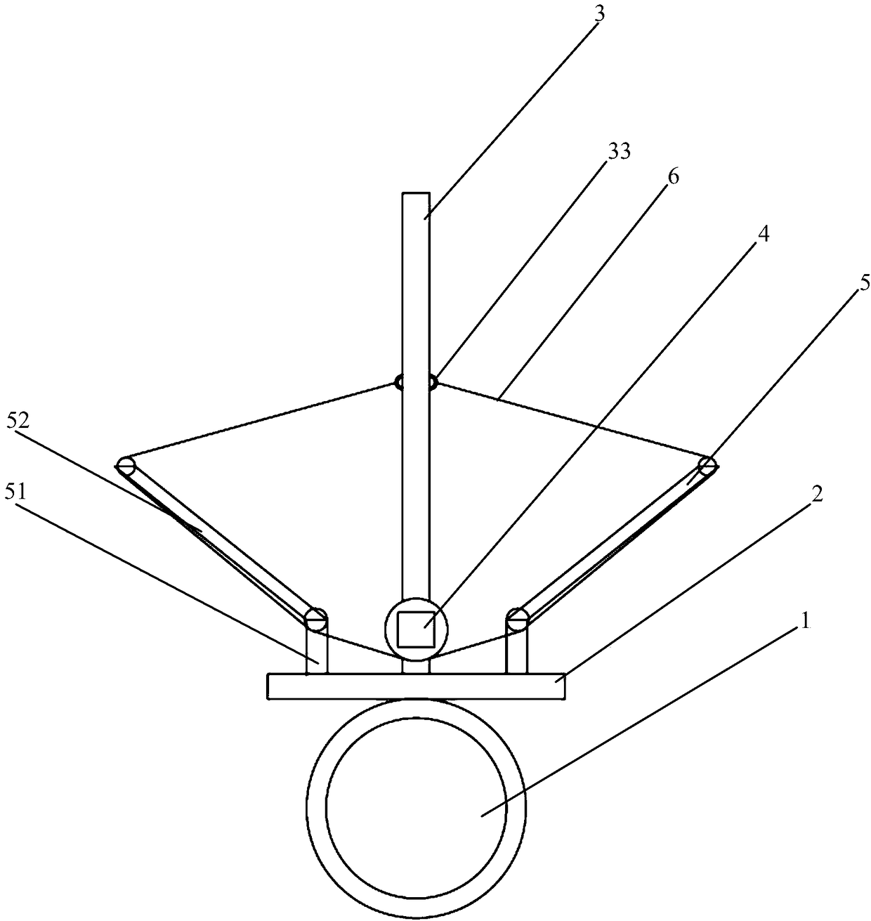
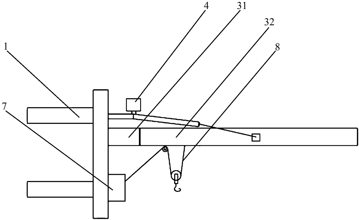
[0020] A kind of simple lift provided by the present invention, such as Figure 1 to Figure 3 As shown, it includes a clamp 1, a connecting plate 2, a main rod 3, a first motor 4, two extension rods 5, two traction ropes 6, a second motor 7 and a pulley block 8. Wherein, the middle part of one side of the connecting plate 2 is provided with a clamp 1, the middle part of the other side of the connecting plate 2 is provided with a main rod 3, and the first motor 4 is fixed to the connecting plate 2 directly above the main rod 3, two The extension rods 5 are respectively fixed to the connecting plate...


PUM


Abstract

A simple lifter comprises a hoop, a connecting plate, a main rod, a first motor, two extension rods, two pulling ropes, a second motor and a pulley block. The hoop is arranged in the middle of one side of the connecting plate, the main rod is arranged in the middle of the other side of the connecting plate, the first motor is positioned above the main rod and fixed to the connecting plate, the two extension rods are positioned on two sides of the first motor and fixed to the connecting plate, the main rod is respectively connected with rotors of the first motor through the two pulling ropes, the second motor is positioned below the main rod and arranged on the connecting plate, the pulley block is arranged below the main rod, and one end of the pulley block is connected with the second motor. The simple lifter is simple in structure, convenient to carry and flexible to use and can be widely popularized.

Description

technical field [0001] The invention relates to the field of machinery, in particular to a simple elevator. Background technique [0002] When setting the utility poles, it is necessary to install a disconnector on the utility pole, but the disconnector is of high quality, and moving the disconnector to the utility pole with a height of more than ten meters is prone to accidents, and the work efficiency is low. Contents of the invention [0003] Aiming at the above-mentioned problems in the prior art, the purpose of the present invention is to provide a simple elevator to save manual labor and improve work efficiency. [0004] In order to realize the foregoing invention object, the technical scheme that the present invention adopts is as follows: [0005] A simple elevator, including a clamp, a connecting plate, a main rod, a first motor, two extension rods, two traction ropes, a second motor and a pulley block, wherein a clamp is arranged in the middle of one side of the...

Claims


Application Information

Patent Timeline
Patent Type & Authority Patents(China)
IPC IPC(8): B66D3/20B66D3/26
CPCB66D3/20B66D3/26
Inventor 杨焘张鹏翟国柱侯睿杨栋
Owner 江苏省电力公司太仓市供电公司
Learn More