Shunting device for pipeline electrolyzer

A shunt device and electrolytic cell technology, applied in the field of electrolysis, can solve the problems of long concentration adjustment process, damage to the cell body, and inability to adjust the current independently, and achieve the effects of stable and reliable structure, large resistance, and avoiding high-temperature melt leakage.

Active Publication Date: 2017-01-04
PANGANG GROUP TITANIUM INDAL
View PDF3 Cites 0 Cited by
  • Summary
  • Abstract
  • Description
  • Claims
  • Application Information

AI Technical Summary

Problems solved by technology

However, all the electrolyzers in the pipeline electrolyzer are a system, and the current cannot be adjusted individually
Under normal circumstances, when the tank temperature is too high, adjusting the tank temperature through the concentration is the fundamental solution to the problem, but the characteristics of

Method used


Image

  • Shunting device for pipeline electrolyzer
  • Shunting device for pipeline electrolyzer
  • Shunting device for pipeline electrolyzer

Examples


Embodiment Construction

[0016] The present invention is further described below by accompanying drawing.

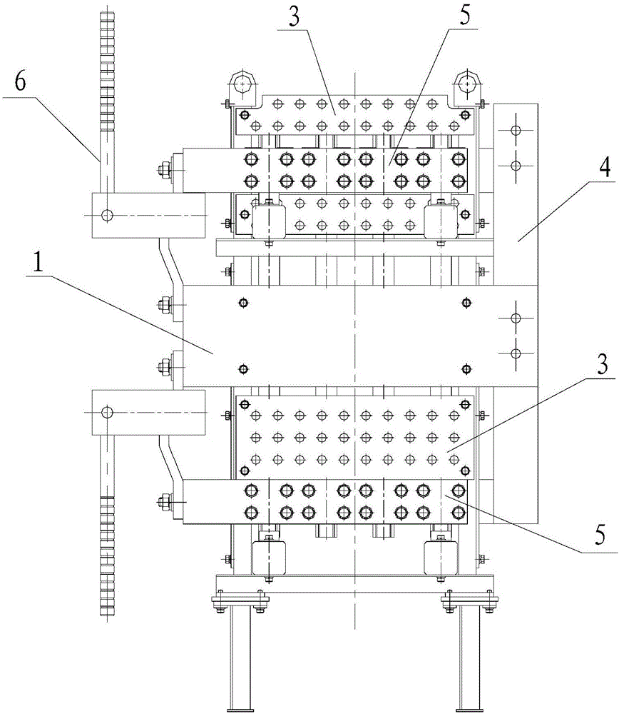
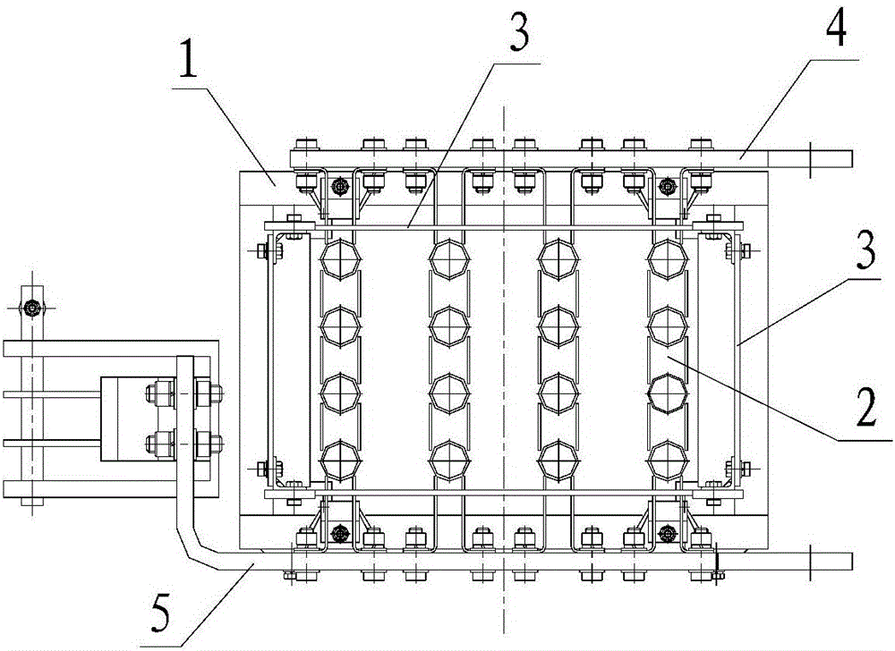
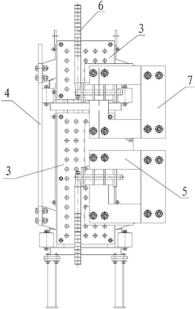
[0017] Such as figure 1 As shown, the present invention includes a plurality of shunt bodies that can be connected in series with the line electrolyzer, and the shunt body includes an installation frame 1 and a resistance assembly 2 located in the installation frame 1, and an insulating plate is arranged around the resistance assembly 2 3. One side of the installation frame 1 is provided with a busbar connection plate 4, and the other side is provided with a slot end connection plate 5. The installation frame 1 mainly plays the role of supporting, fixing and connecting the resistance assembly 2. The insulation board 3 is arranged around the resistance assembly 2. Except for the position of the installation frame 1, the rest of the parts are surrounded by the insulation board 3. In addition to the insulation function, the insulation board 3 also It can protect the resistance component 2 to a cer...


PUM


Abstract

The invention discloses a shunting device for a pipeline electrolyzer in the technical field of electrolysis. The device comprises a plurality of shunt main bodies which can be connected in series with the pipeline electrolyzer, and is characterized in that each shunt main body comprises a mounting frame and a resistor component located in the mounting frame, wherein insulating plates are arranged around the resistor component, a busbar connecting plate is arranged on one side of the mounting frame and a groove end connecting plate is arranged on the other side of the mounting frame. The shunting device for the pipeline electrolyzer disclosed by the invention has the beneficial effects that each shunt comprises the mounting frame, the resistor component and the insulating plates, thereby having a stable and reliable structure, and providing greater resistance, when an individual electrolyzer has too-high temperature caused by reasons of the concentration and the like, the shunt can be accessed to lower the current of the individual electrolyzer, so that the electrolyzer temperature is controlled in a short period of time to avoid situations of high-temperature melt leakage and the like of an electrolyzer body.

Description

technical field [0001] The invention relates to the technical field of electrolysis, in particular to a flow splitting device for an electrolyzer on a pipeline. Background technique [0002] When using electrolytic cells for industrial production, currently domestic electrolytic cells use multi-stage cells. When the temperature of individual electrolytic cells is too high or leakage occurs, the electrolytic cell can be adjusted and controlled by adjusting the current and dismantling the cathode and anode. . However, all the electrolyzers in the line electrolyzer are a system, and the current cannot be adjusted individually. Under normal circumstances, when the tank temperature is too high, adjusting the tank temperature through the concentration is the fundamental solution to the problem, but the characteristics of the pipeline electrolyzer make the concentration adjustment process longer. If the temperature of the electrolytic cell is too high for a long time, it will eas...

Claims


Application Information

Patent Timeline
IPC IPC(8): C25C7/06C25B15/02C25B9/18C25B9/04
CPCC25B15/02C25C7/06C25B9/65C25B9/70
Inventor 赵鑫尹德知陈勇
Owner PANGANG GROUP TITANIUM INDAL
Why Eureka
Try Eureka