Intelligent clothes airing device

An intelligent, clothes-drying technology, applied in washing devices, other drying devices, textiles and papermaking, etc., can solve the problems of not easy drying, cause colds, affect the shape of clothes, etc., and achieve the effect of increasing air flow and increasing air flow. , the effect of accelerated drying

Active Publication Date: 2017-01-04
NINGBO FEIERGE ELECTROMECHANICAL TECH CO LTD
View PDF6 Cites 1 Cited by
  • Summary
  • Abstract
  • Description
  • Claims
  • Application Information

AI Technical Summary

Problems solved by technology

[0002] Clothes hangers are household items commonly used in people’s lives. The traditional clothes hangers on the market have a single structure and are formed by integral injection molding; clothes to dry
[0003] But the existing clothes hanger is generally bent into a skeleton by one-piece molding, therefore, when drying clothes, this kind of clothes hanger can stretch out the sleeves of both sides of the clothes, thereby allowing air to blow through the cloth in a large area and can Dry clothes, but because the clothes hanger of this kind of shape only relies on the tube surface to support the clothes, it will make the clothes easy to produce the creases of the hangers at the shoulders, which seriously affects the shape of the clothes; and the clothes hanger is drying the clothes The position of the sleeves is often close to the front and back of the clothes, and the position of the sleeves is not easy to be blown and exposed by the wind, and it is the least easy to dry. Often the bottom of the sleeves is still wet when other parts of the clothes are dry. At this time, if people put it into the wardrobe, it is easy to be in a state of inconvenient ventilation of the wardrobe when the sleeves are wet, resulting in heavy humidity and mildew; and if people wear it on the body, the sleeves are still damp. state, it is easy to affect people's wearing comfort, and even cause cold problems

Method used


Image

  • Intelligent clothes airing device
  • Intelligent clothes airing device
  • Intelligent clothes airing device

Examples


Embodiment Construction

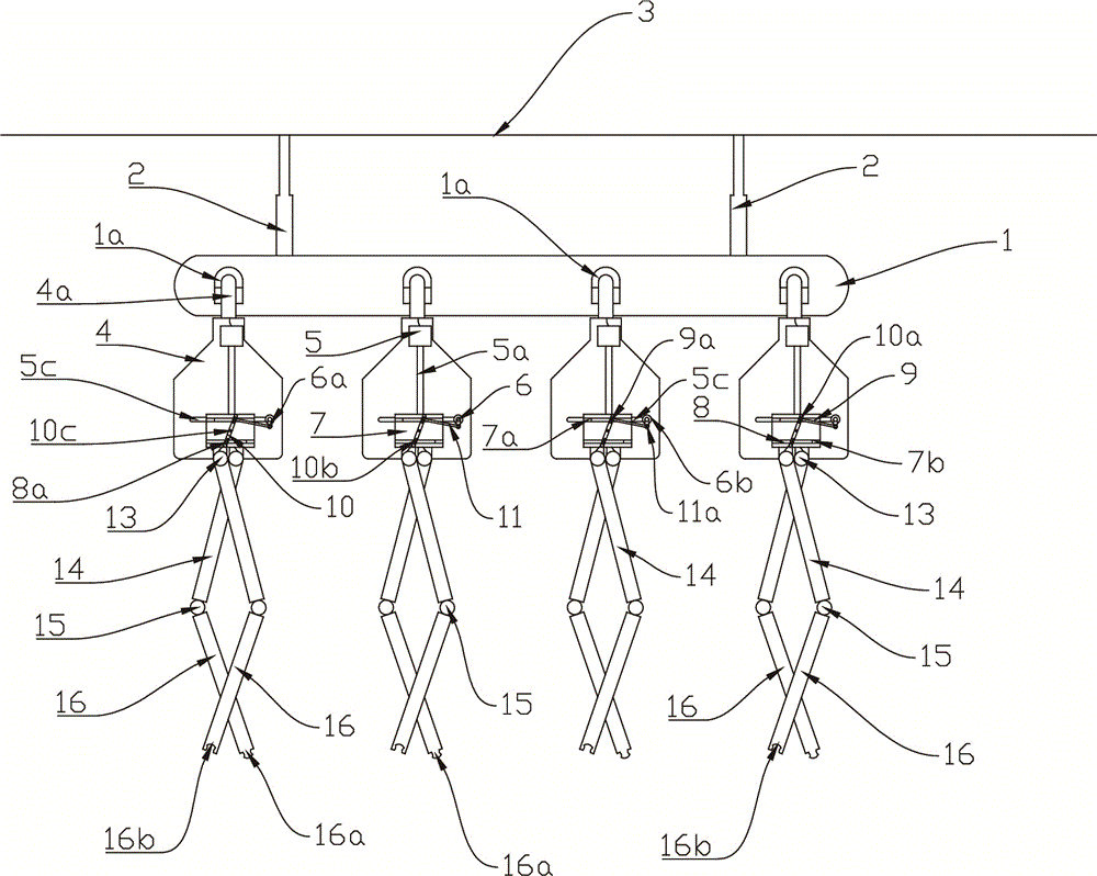
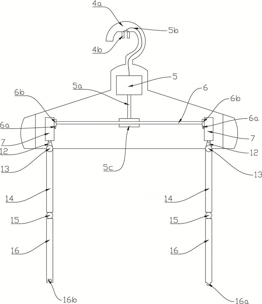
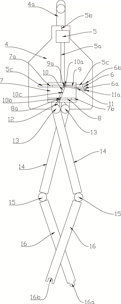
[0011] The present invention will be further described below in conjunction with the accompanying drawings and specific embodiments.

[0012] See Figure 1 to Figure 3 , an intelligent clothes-drying device, comprising a lifting rod 2, a clothes-drying horizontal rod 1 and a plurality of clothes-drying racks 4, the lifting rod 2 is arranged under the roof 3, and a clothes-drying horizontal rod 1 is arranged under the lifting rod 2, so that A number of clothes drying holes 1a are arranged on the clothes drying horizontal bar 1, a clothes drying hook 4a is arranged on the clothes drying rack 4, a jack is arranged in the clothes drying hole 1a, and a plug is arranged under the clothes drying hook 4a 4b, the clothes hanger 4 is fixed by inserting the plug 4b under the clothes hanger 4a into the jack in the clothes hole 1a; a motor 5 is also arranged in the middle of the clothes hanger 4, and the plug 4b connects with the clothes hanger through the electric wire 5b The motor 5 in ...


PUM


Abstract

The invention discloses an intelligent clothes airing device. Rotary worm gears driven by motors drive worms to rotate to enable second rotary rods located on two sides of each worm and connected with the worm to rotate, so that the second rotary rods drive fourth connecting rods to rotate, the fourth connecting rods pull first sliding strips to slide on upper tracks, first bulging blocks on the first sliding strips penetrate first kidney-shaped holes in third rotary rods and are connected with the fourth connecting rods, the fourth connecting rods are enabled to swing along second rotary shafts, third rotary shafts connected below the fourth connecting rods through connecting blocks can be also driven to swing, first swing rods are connected to the lower parts of the third rotary shafts and connected with second swing rods through second rotary shafts, the first swing rods and the second swing rods can realize a human hand swing effect, clothes sleeves extending into the first swing rods and the second swing rods are swung, the air movement effect is improved, swing-drying of the clothes sleeves is accelerated, and the condition that the sleeves are still wet while the clothes are dried are still wet is prevented.

Description

technical field [0001] The invention relates to the field of household daily necessities, in particular to an intelligent clothes drying device. Background technique [0002] Clothes hangers are household items commonly used in people’s lives. The traditional clothes hangers on the market have a single structure and are formed by integral injection molding; Laundry to dry. [0003] But the existing clothes hanger is generally bent into a skeleton by one-piece molding, therefore, when drying clothes, this kind of clothes hanger can stretch out the sleeves of both sides of the clothes, thereby allowing air to blow through the cloth in a large area and can Dry clothes, but because the clothes hanger of this kind of shape only relies on the tube surface to support the clothes, it will make the clothes easy to produce the creases of the hangers at the shoulders, which seriously affects the shape of the clothes; and the clothes hanger is drying the clothes The position of the sl...

Claims


Application Information

Patent Timeline
Patent Type & Authority Applications(China)
IPC IPC(8): D06F57/12
CPCD06F57/125
Inventor 赵广静
Owner NINGBO FEIERGE ELECTROMECHANICAL TECH CO LTD
Why Eureka
Try Eureka