Water storage structure of urban runoff unit

An urban and runoff technology, applied in drainage structures, water supply devices, waterway systems, etc., can solve the problems of difficult cleaning, high cost, easy silting, etc., and achieve the effect of alleviating urban water shortage, low maintenance cost, and simple maintenance.

Inactive Publication Date: 2017-01-04
CHONGQING BUREAU OF GEOLOGY & MINERAL EXPLORATION & DEV NO 208 HYDROGEOLOGICAL & ENG GEOLOGICAL TEAM
View PDF4 Cites 4 Cited by
  • Summary
  • Abstract
  • Description
  • Claims
  • Application Information

AI Technical Summary

Problems solved by technology

[0004] First, the city is "an inch of land and an inch of gold", and it is impossible to build urban green spaces in a scattered and large area, which will cause difficulties in the construction of sponge cities;
[0005] Second, the old city that has been built involves a series of problems such as demolition, which is not convenient for the overall planning and implementation of the sponge city;
[0006] Third, the area covered by the sponge city is too small compared to the overall area of ​​the city. Its principle is to use "modular" water absorption and storage, and its water absorption and storage capacity is very weak. Appears powerless during heavy rain;
[0007] Fourth, the modular water absorption and storage mechanism used in the "sponge city" is prone to fouling and difficult to clean. After one year of operation, it may become severely silted and lose its water absorption and storage function;
[0008] Fifth, the cost of "sponge city" is high, reaching 100-150 million yuan per square kilometer

Method used


Image

  • Water storage structure of urban runoff unit
  • Water storage structure of urban runoff unit
  • Water storage structure of urban runoff unit

Examples


Embodiment Construction

[0026] Below by embodiment and in conjunction with accompanying drawing, the present invention will be further described:

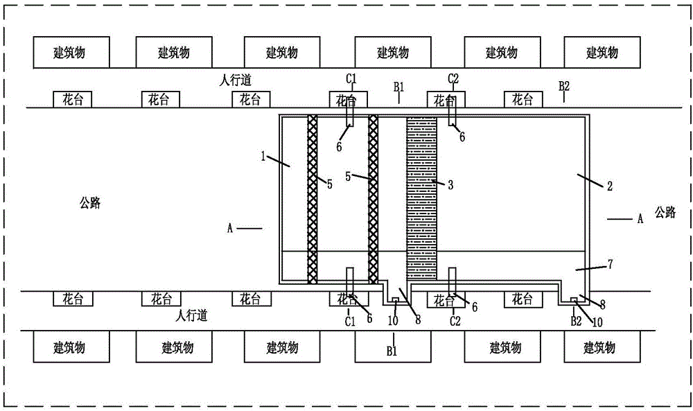
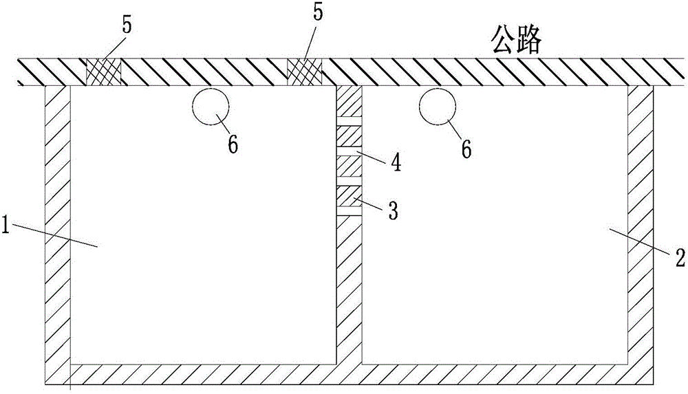
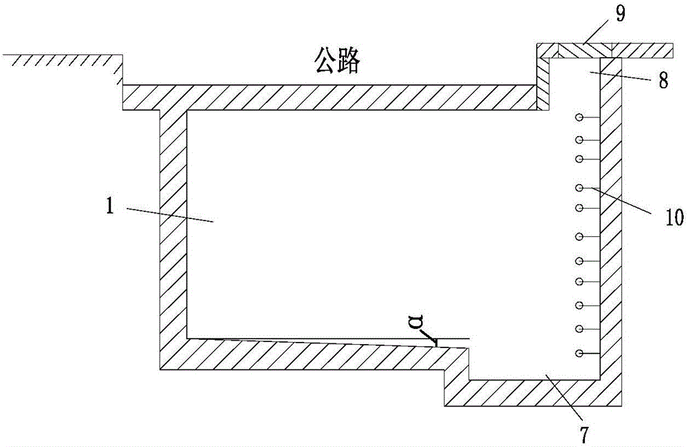
[0027] combine figure 1 — Figure 5 As shown, a water storage structure of an urban runoff unit is composed of a sedimentation tank 1, a storage tank 2, a separation wall 3, a water hole 4, a water grate 5, a ventilation pipe 6, a dredging tank 7, a sewage outlet 8, a sewage discharge Port cover plate 9, pedestrian ladder 10, air vent filter screen 11 and water hole filter screen 12 form.

[0028] Sedimentation tank 1 and storage tank 2 are built under the urban highway, and are arranged one after the other along the extension direction of the urban highway. The sedimentation tank 1 and storage tank 2 are almost as wide as the urban road, so as to improve the sedimentation tank 1 with the same length. and the volume of the reservoir 2. Restored municipal roads are built above the sedimentation tank 1 and the reservoir 2 without affecting the traffic of...


PUM


Abstract

The invention discloses a water storage structure of an urban runoff unit. A settling tank and a water storage tank are built under an urban highway, water passing holes are formed in the upper portion of an isolation wall between the settling tank and the water storage tank, a shutter grate is arranged above the settling tank, the settling tank and the water storage tank are provided with ventilation pipelines communicated with the outside, the upper ends of the ventilation pipelines are placed into a flower bed of a sidewalk and used for exhausting air in the settling tank and the water storage tank, dredging grooves are formed in the bottom of one side of the settling tank and in the bottom of one side of the water storage tank and are lower than the settling tank and the water storage tank, the bottoms of the settling tank and the water storage tank are gradually inclined along the direction of the dredging grooves to form inclined surfaces with slopes alpha, drain outlets are formed in the upper portions of the settling tank and the water storage tank respectively and sealed by drain outlet cover plates, and walking ladders aligned to the respectively corresponding drain outlets are arranged in the settling tank and the water storage tank. The water storage structure is low in cost, high in water storage capacity and implementation feasibility and thoroughly solves the problem of urban inland inundation, and accumulated rainwater can be reused.

Description

technical field [0001] The invention relates to the technical field of municipal engineering, in particular to a runoff unit water storage structure for solving urban waterlogging. Background technique [0002] At this stage, there is no way to use water storage to solve the urban waterlogging problem. The general practice is to use existing urban green spaces and sidewalks to rebuild "sponge cities". The international general term is "low-impact development rainwater system construction". The stored water is "released" and used. [0003] There is a problem: [0004] First, the city is "an inch of land and an inch of gold", and it is impossible to build urban green spaces in a scattered and large area, which will cause difficulties in the construction of sponge cities; [0005] Second, the old city that has been built involves a series of problems such as demolition, which is not convenient for the overall planning and implementation of the sponge city; [0006] Third, t...

Claims


Application Information

Patent Timeline
Patent Type & Authority Applications(China)
IPC IPC(8): E03F5/10E03F5/14
CPCY02A10/30E03F5/10E03F5/14
Inventor 任良治任柏橙
Owner CHONGQING BUREAU OF GEOLOGY & MINERAL EXPLORATION & DEV NO 208 HYDROGEOLOGICAL & ENG GEOLOGICAL TEAM
Why Eureka
Try Eureka