Sidewalk integrated pipe network and water storage and drainage system

A technology for water storage and sidewalks, which is applied to waterway systems, sewer systems, drainage structures, etc., can solve problems such as high expansion costs, poor drainage capacity, and difficult maintenance in the later period, and achieve increased greening area, convenient maintenance, and maintenance costs low effect

Active Publication Date: 2018-01-05
衡阳市金泓建筑装饰设计有限公司
View PDF6 Cites 0 Cited by
  • Summary
  • Abstract
  • Description
  • Claims
  • Application Information

AI Technical Summary

Problems solved by technology

It solves the problems of high cost of reconstruction and expansion of the urban comprehensive pipeline network, poor drainage capacity, and difficult maintenance in the later stage, and improves the safety performance of the urban comprehensive pipeline network and reduces the difficulty of construction. It also provides convenience for the later maintenance of the comprehensive pipeline network condition

Method used


Image

  • Sidewalk integrated pipe network and water storage and drainage system
  • Sidewalk integrated pipe network and water storage and drainage system
  • Sidewalk integrated pipe network and water storage and drainage system

Examples


Embodiment 1

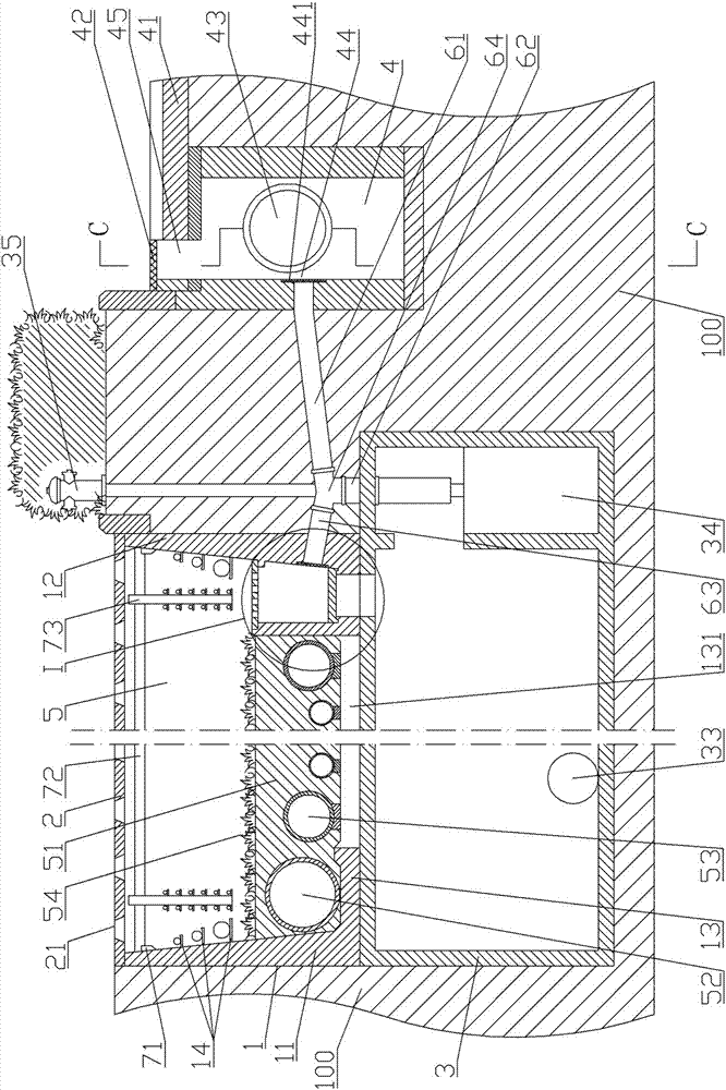
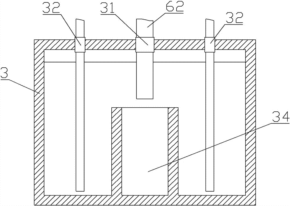
[0067] like Figure 1-8 Shown: a sidewalk comprehensive pipe network and storage and drainage system, including a U-shaped ditch 1, a hollow floor 2, a water storage tank 3, a water collection well 4 and water pipe components.

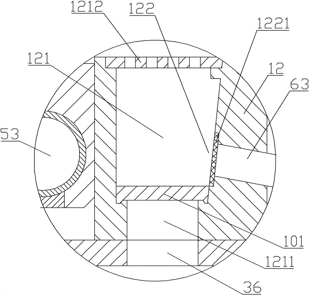
[0068] The U-shaped ditch 1 includes a left wall 11, a right wall 12 and a connecting plate 13 connected to the lower ends of the left wall and the right wall. The lower end of the right wall 12 is provided with a drainage ditch 121, and the upper end of the drainage ditch 121 is provided with a permeable cover plate B1212. The side wall of the right wall 12 is provided with a water inlet A122 communicating with the drainage ditch 121, and a filter screen B1221 is arranged at the water inlet A122. Water leakage holes 131 are arranged at intervals on the connecting plate 13 to facilitate rainwater to infiltrate into the soil 100 . The U-shaped ditch 1 can be built by masonry, cast-in-situ or prefabricated. When the U-shaped grooves 1 are criss-crosse...

Embodiment 2

[0082] like Figure 9 , 10 As shown, compared with Embodiment 1, the present embodiment differs only in that:

[0083] Slide bar beam 72 is square steel. The sliding assembly includes a pulley shaft 753 and a pulley 754; the two ends of the pulley shaft 753 are installed on the two side walls of the vertical hanging beam 73, and the pulley 754 is movably installed on the pulley shaft 843, and is positioned in the axial direction, and is located in the vertical Between the two side walls of the hanging beam 73 and in the roller groove on the upper end of the sliding bar beam 72 , the vertical hanging beam 73 can slide on the sliding bar beam 72 through the pulley 754 .

[0084] Briefly describe the application of the present invention: the sidewalk 21 and the driveway 41 are respectively located on both sides of the green belt. When the rainstorm comes, the rainwater first enters the water collection well 4 below the two sides of the roadway 41, and then is discharged into t...


PUM


Abstract

Provided is a sidewalk integrated pipe network and water storage and drainage system, including water-collecting wells, U-shaped grooves, hollowed-out bottom plates, water storage tanks, and water pipe assemblies. The U-shaped groove comprises a left wall, a right wall, and a connecting plate connected with the lower ends of the left wall and the right wall. The connecting plate is provided with leakage holes at interval. The hollowed-out bottom plates are pavement of a sidewalk, and are arranged on the upper ends of the U-shaped grooves. An overhead cavity is formed between the hollowed-out bottom plate and the U-shaped groove. The water storage tank is arranged under the U-shaped groove. A water inlet B and a water outlet B are arranged on the water storage tank. The water outlet B is communicated with a water utilization terminal, and adjacent water storage tanks are communicated through water pipes A. The water pipe assemblies communicate water outlets A of the water-collecting wells with water inlets A of the U-shaped groove, and communicate water outlets A of the water-collecting wells with water inlets B of the water storage tanks. The system is advantaged by accommodating acity integrated pipe network, having a water storage function, preventing urban inland inundation, and preventing a lake on a road.

Description

technical field [0001] The invention relates to an urban drainage pipe network system, in particular to a sidewalk comprehensive pipe network and storage and drainage system. Background technique [0002] Many cities in our country will experience waterlogging when they encounter heavy rainfall. In addition to the high frequency of extremely bad weather, there are also problems in urban construction itself. A large number of hard pavements, such as asphalt roads and cement pavements, have poor permeability when it rains, are not easy to infiltrate, and easily form water accumulation on the road surface. The urban comprehensive pipe network system that does not match the speed of urban development is the most important factor that causes waterlogging. [0003] Therefore, there are two main factors causing the current urban waterlogging problem: one is the deficiency of the existing urban comprehensive drainage pipe network system, and the other is that the urban road surface...

Claims


Application Information

Patent Timeline
Patent Type & Authority Applications(China)
IPC IPC(8): E03F3/04E03F5/04E03F5/06E03F5/10
CPCE03F3/04E03F5/0401E03F5/06E03F5/10E03F2201/00
Inventor 谢金钊谢飞帆陶林辉
Owner 衡阳市金泓建筑装饰设计有限公司
Why Eureka
Try Eureka