
A locking device for urban rail vehicles and bus door systems

A technology for public transport vehicles and urban rails, which is applied to electric locks, power transmission/actuator features, etc., and can solve problems such as difficulty in replacement, damage to locking device parts, and failure to consider the meshing fit of the end toothed disc and the end toothed shaft.

Active Publication Date: 2019-02-12
NINGBO CRRC TIMES TRANSDUCER TECH CO LTD
View PDF4 Cites 0 Cited by
  • Summary
  • Abstract
  • Description
  • Claims
  • Application Information

AI Technical Summary

Problems solved by technology

[0006] For the first type of locking mechanism, the locking effect can only be achieved after the door is closed in place. The disadvantage of this device is that the screw pitch on the screw is changed, the screw is not easy to process, and the screw is worn after the locking section is worn. The bar is not easy to replace
[0007] For the second type of locking mechanism, the locking block bears the force of the finger guard rubber strip and is a vulnerable part. The limit protrusion is not rigidly fixed, which causes the door leaf to jump easily during the door opening and closing process.
[0008] The third type of locking mechanism is full-range locking, which requires high installation accuracy and achieves full-range locking, but does not consider the meshing degree of the end gear plate and the end gear shaft, and parts of the locking device will also appear during use. The problem of damage and difficult replacement

Method used


Image

  • A locking device for urban rail vehicles and bus door systems
  • A locking device for urban rail vehicles and bus door systems
  • A locking device for urban rail vehicles and bus door systems

Examples


Embodiment Construction

[0023] The present invention will be further described below in conjunction with the embodiments of the accompanying drawings.

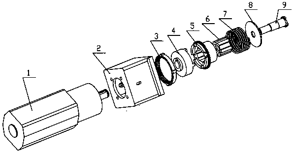
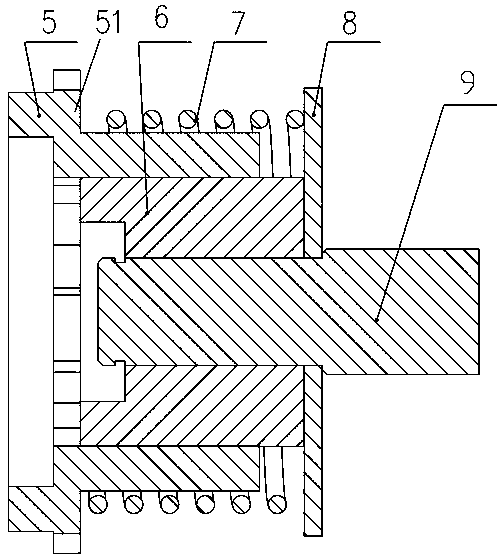
[0024] Such as figure 1 , 2 , 3, and 6, a locking device for urban rail vehicles and bus door systems mainly includes a driving part and a driven part. In the figure, 1 is a motor, 2 is a connecting sleeve, 3 is an internal gear, and 4 Be a sleeve, 5 is an external gear, 6 is a spline sleeve, 7 is a spring, 8 is a baffle plate, and 9 is a screw mandrel.

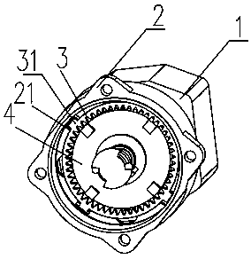
[0025] active part as figure 2 As shown, it includes a motor 1, a connecting sleeve 2, an internal gear 3, and a sleeve 4.

[0026] The motor 1 is rigidly connected to the connecting sleeve 2 , and the shaft 11 of the motor 1 is connected to the sleeve 4 through a key 41 .

[0027] A groove 21 is arranged in the inner cavity of the connecting sleeve 2 along the circumference, and a protrusion 31 is correspondingly arranged on the internal gear 3 . Since the internal gear 3 is embedded in the g...


PUM


Abstract

The invention discloses a locking device for door systems of urban rail vehicles and public transport vehicles. The locking device comprises a driving part and a driven part, wherein the driving part comprises a motor, a connecting sleeve, an internal gear and a sleeve; the motor is rigidly connected with the connecting sleeve; a shaft of the motor is connected with the sleeve through a bond; the internal gear is fixed in an inner cavity of the connecting sleeve; the driven part comprises an external gear, a spline sleeve, a spring, a baffle plate and a screw; the external gear sleeves outside the spline sleeve; the spring sleeves outside the external gear; one side of the spring is limited by a fluted disc of the external gear; the other end of the spring is limited by the baffle plate; the baffle plate is fixed on the screw; the interior of the spline sleeve is connected with the screw through the bond; the driving part is connected with the driven part through the internal gear of the driving part and the external gear of the driven part; in a normal state, the internal gear is meshed with the external gear; when the motor rotates and the sleeve is centrifuged to move to separate the external gear from the internal gear, the driven part can be rotated.

Description

technical field [0001] The invention relates to an unlocking door transmission mechanism of a locomotive door. Background technique [0002] The locking devices of the vehicle door systems of existing rail vehicles and public transport vehicles have the following types. [0003] The first is a passive locking device, which is realized by changing the lead of the screw. Its biggest feature is that the spiral groove of the screw with a rising angle is divided into two sections. Its structure includes variable lift angle screw rod, ordinary nut, torsion spring, screw sleeve, contact pin and manual unlocking part. The helical groove of the variable lead angle screw is divided into two sections, one is a helical groove with a large lead angle and high-efficiency transmission, and its end is connected with a small section of helical groove with a helix angle smaller than the friction angle to form a locking section. The locking and unlocking of the door is realized by the self-a...

Claims


Application Information

Patent Timeline
Patent Type & Authority Patents(China)
IPC IPC(8): E05B81/06E05B81/34E05B81/32
CPCE05B81/06E05B81/32E05B81/34
Inventor 黄兵彭毅沈敏杰华聪立
Owner NINGBO CRRC TIMES TRANSDUCER TECH CO LTD
Learn More