Capacitive sensor anti-pinch detection device for sliding doors
A capacitive sensor and detection device technology, applied in door/window accessories, power control mechanisms, wing leaf control mechanisms, etc., to achieve the effects of low standby power consumption, not easy to be triggered by mistake, and long service life
- Summary
- Abstract
- Description
- Claims
- Application Information
AI Technical Summary
Problems solved by technology
Method used
Image

Examples
Embodiment 1
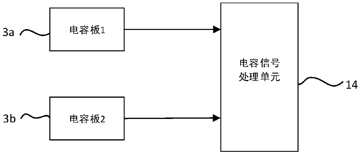
[0051]The first capacitor plate 3a and the second capacitor plate 3b can be fixedly arranged on the sliding doors 1, 2, and move synchronously with the opening and closing of the sliding doors 1, 2;
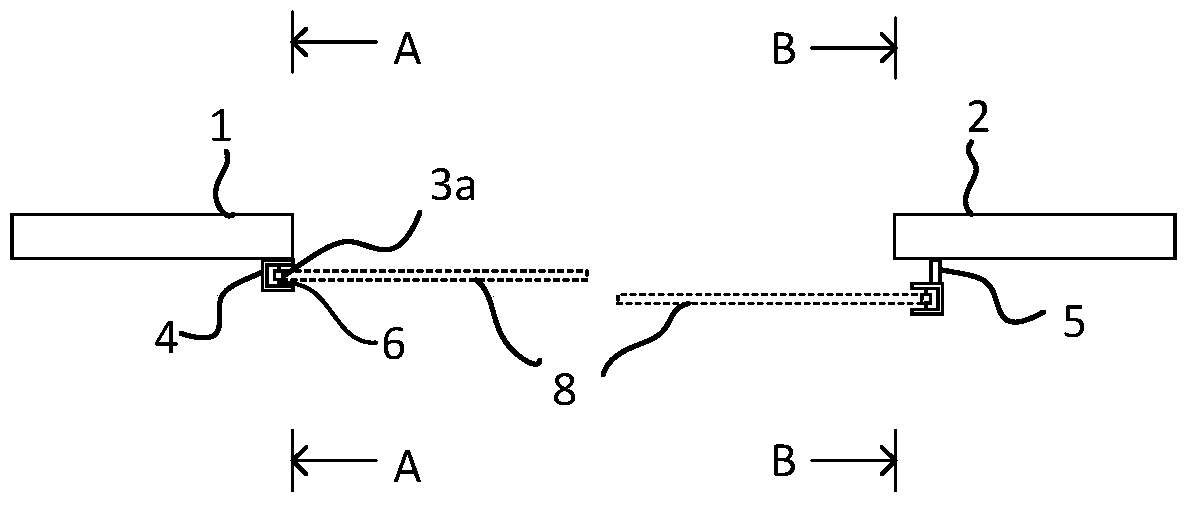
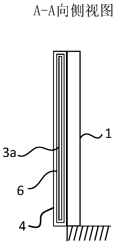
[0052] like Figure 2 to Figure 4 As shown, the metal shielding plate 4 of the first capacitor plate 3a is fixedly arranged on the first sliding door 1, and the metal shielding plate 4 of the second capacitor plate 3b is fixedly arranged on the second sliding door 2 through the connecting rod 5, so that the two The two capacitive plates 3a, 3b are staggered from each other in the direction of motion to ensure that the two do not interfere with each other when moving with the sliding doors 1, 2;
[0053] After such arrangement, the effective sensing areas 8 on both sides are less likely to interfere with each other during the movement of the sliding doors 1 and 2 .
Embodiment 2
[0055] The first capacitor plate 3a and the second capacitor plate 3b can also be arranged on the outside of the sliding doors 1, 2, and are fixedly installed by the fixed column 9, and do not move with the sliding doors 1, 2;
[0056] like Figure 5 As shown, the metal shielding plates 4 of the two capacitor plates 3a, 3b are respectively fixed on the outside of the sliding door opening and closing space formed by the sliding doors 1, 2 through the fixing columns 9, and do not move with the sliding doors 1, 2.
Embodiment 3
[0058] The first capacitive plate 3a and the second capacitive plate 3b can also be arranged above and / or below the sliding door opening and closing space formed by the sliding doors 1, 2, and do not move with the sliding doors 1, 2;
[0059] like Image 6 As shown, the metal shielding plates 4 of the two capacitive plates 3a, 3b are respectively fixed on the bottom door frames of the sliding doors 1, 2, and do not move with the sliding doors 1, 2.
[0060] like Figure 7 As shown, the metal shielding plates 4 of the two capacitor plates 3a, 3b are respectively fixedly arranged on the bottom door frame and the top door frame of one of the sliding doors 1, and do not move with the sliding doors 1, 2;
PUM
 Abstract
Description
Claims
Application Information