Clutch system and clutch separation bearing assembly

A technology for separating bearings and clutches, applied in clutches, fluid-driven clutches, mechanical-driven clutches, etc., can solve problems such as difficulties in automatic centering, achieve the effects of reducing noise pollution, improving service life, and reducing friction loss

Inactive Publication Date: 2017-01-04
SCHAEFFLER TECH AG & CO KG
View PDF13 Cites 1 Cited by
  • Summary
  • Abstract
  • Description
  • Claims
  • Application Information

AI Technical Summary

Problems solved by technology

[0007] The problem solved by the present invention is that the automatic centering of the existing clutch release bearing becomes difficult when the clutch is in the engaged state, resulting in relative sliding between the diaphragm spring and the release bearing

Method used


Image

  • Clutch system and clutch separation bearing assembly
  • Clutch system and clutch separation bearing assembly
  • Clutch system and clutch separation bearing assembly

Examples


no. 1 example

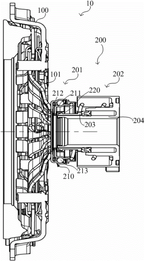
[0030] refer to image 3 , the present embodiment provides a clutch system 10, including: a clutch 100 including a diaphragm spring 101; a clutch operating mechanism 200 for controlling disengagement and engagement of the clutch 100. The clutch operating mechanism 200 includes: a release bearing assembly 201 ; and a coaxial slave cylinder (Concentric Slave Cylinder, CSC for short) 202 . The coaxial slave cylinder 202 includes: a guide sleeve 204, which has a through hole (not marked) for accommodating the input shaft of the gearbox; an annular piston 203 movably sleeved outside the guide sleeve 204, located along Axially away from the side of the clutch 100 .

[0031] refer to image 3 and Figure 4 , The release bearing assembly 201 includes: a support ring 220 connected to the piston 203 in the axial direction; an annular elastic member 230 sleeved outside the support ring 220 ; The release bearing 210 has an inner ring 211 and an outer ring 212 arranged coaxially, and a...

no. 2 example

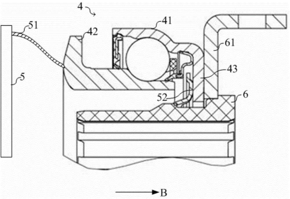
[0049] Compared with the first embodiment, the second embodiment differs in that:

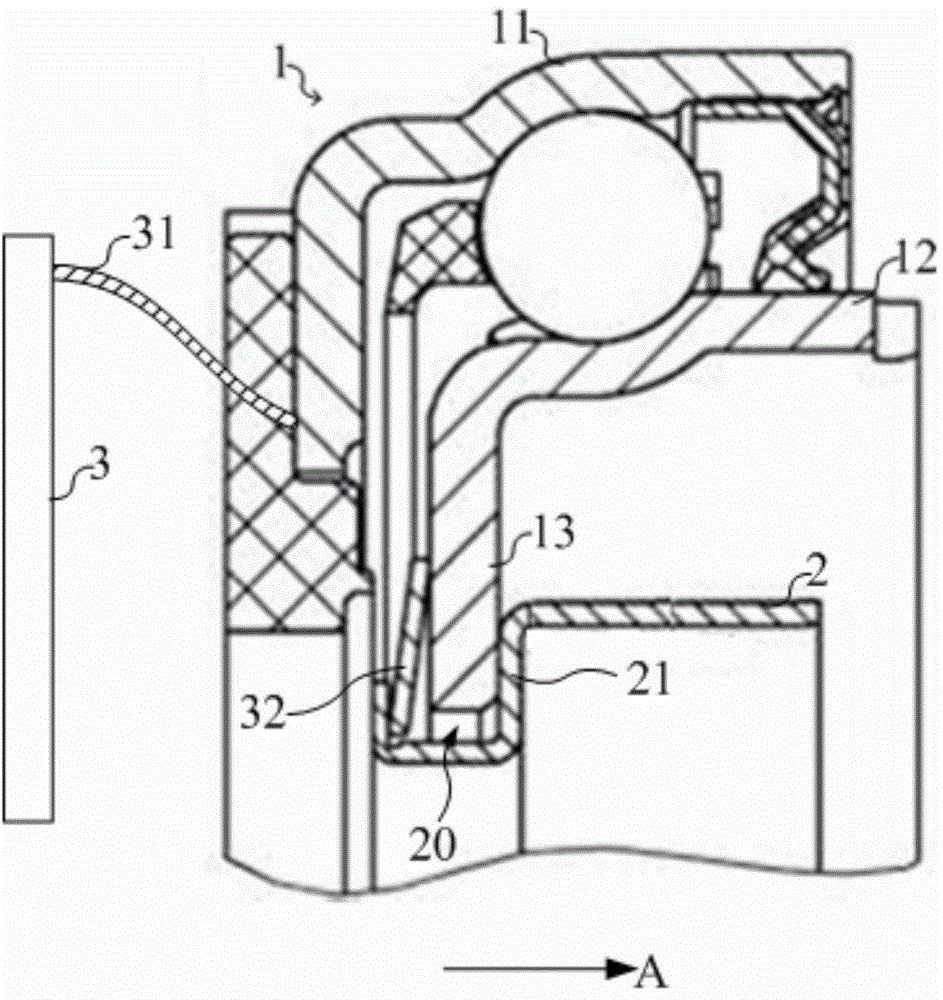
[0050] refer to Image 6 , in the release bearing 300, the inner ring 311 is a rotatable ring and the outer ring 312 is a non-rotating ring. The clutch 400 resists the inner ring 311 through the diaphragm spring 401, and the diaphragm spring 401 can rotate synchronously with the inner ring 311, wherein on the side of the release bearing 300 axially away from the clutch 400, the annular piston (not shown in the figure) ) is used to drive the outer ring 312 to move the release bearing 300 axially;

[0051] The outer ring 312 is provided with a first protrusion 314 protruding radially toward the support ring 320 and surrounding the support ring 320; the outer peripheral surface of the support ring 320 is provided with an annular protrusion 321 protruding radially toward the outer ring 312. 300 is provided with an annular stopper 322 on the side away from the clutch 400 in the axial direction, an...


PUM


Abstract

The invention discloses a clutch system and a clutch separation bearing assembly. The clutch separation bearing assembly comprises a separation bearing, a fixed block part and an elastic part; the separation bearing is provided with an inner ring and an outer ring which are coaxially arranged, one of the inner ring and the outer ring is a rotatable ring, the other of the inner ring and the outer ring is a non-rotation ring, and the non-rotation ring is provided with a first protruding portion which inwards protrudes in the radial direction; the fixed stop part is arranged on the side, away from a clutch, of the first protruding portion in the axial direction and axially abuts against the first protruding portion; the elastic part is used for providing axial elastic force so as to enable the first protruding portion to abut against the stop part; the first protruding portion abuts against the stop part in an anti-friction manner. Compared with the prior art, the assembly has the beneficial effects that automatic centre changing of the separation bearing becomes easy, the NVH performance of an automobile is improved, and the service life of the separation bearing and the service life of the stop part are long.

Description

technical field [0001] The invention relates to the technical field of automobiles, in particular to a clutch system and a clutch release bearing assembly. Background technique [0002] The existing clutch system includes: a clutch including a diaphragm spring; and a clutch operating mechanism for controlling the separation and engagement of the clutch. [0003] refer to figure 1 , The clutch operating mechanism includes a release bearing 1 and a support ring 2 , and the release bearing 1 is movably sleeved outside the support ring 2 . The release bearing 1 includes: an outer ring 11 and an inner ring 12 , the outer ring 11 abuts against the diaphragm spring 31 in the axial direction, and the two can rotate synchronously. The support ring 2 is provided with an annular groove 20 towards the inner ring 12, and one end of the inner ring 12 is provided with a protrusion 13 extending into the annular groove 20, and a spring 32 is arranged in the groove 20, and the spring 32 exe...

Claims


Application Information

Patent Timeline
Patent Type & Authority Applications(China)
IPC IPC(8): F16D23/14F16C23/08
CPCF16D23/14F16D25/082
Inventor 沈坚韦亚军常小刚
Owner SCHAEFFLER TECH AG & CO KG
Why Eureka
Try Eureka