Double-sided heating steam generator, steam generating device and steam ironing machine

A technology of steam generator and double-sided heating, applied in steam generation, steam generation methods, steam boilers, etc., can solve the problems of low heating efficiency, large power consumption, and large economic burden of electricity cost for ironing clothes, etc., to improve thermal efficiency , the effect of ensuring safety

Active Publication Date: 2018-04-10
邵博言
View PDF7 Cites 0 Cited by
  • Summary
  • Abstract
  • Description
  • Claims
  • Application Information

AI Technical Summary

Problems solved by technology

[0002] The steam generators on the existing market are all heated on one side, the heating efficiency is low, and the power consumption is large. It is a big economic burden for families and clothing stores to iron clothes.

Method used


Image

  • Double-sided heating steam generator, steam generating device and steam ironing machine
  • Double-sided heating steam generator, steam generating device and steam ironing machine
  • Double-sided heating steam generator, steam generating device and steam ironing machine

Examples


Embodiment 1

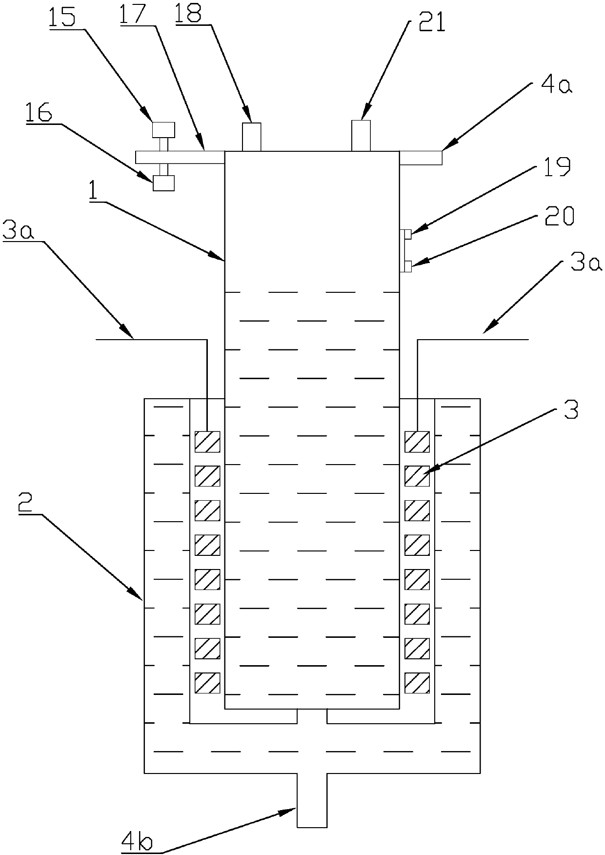
[0029] Such as figure 1 As shown, a double-sided steam generator includes an inner water pipe 1 and an outer water pipe 2 as the casing of the steam generator. The upper part of the inner water pipe 1 is a steam storage chamber, the steam storage chamber is provided with a steam outlet 17, and the lower part is a water storage chamber. The outer water pipe 2 covers the outer periphery of the lower part of the inner water pipe; there is a gap between the outer water pipe 2 and the inner water pipe 1, the gap is used to place the electric heat source 3, and the electric heat source 3 spirally surrounds the outer wall of the inner water pipe 1, two of the electric heat source 3 The electrode 3a protrudes from the upper end of the gap between the outer water pipe and the inner water pipe; the inner surface of the electric heat source 3 is used to heat the inner water pipe 1, and the outer surface of the electric heat source 3 is used to heat the outer water pipe 2; the bottom of th...

Embodiment 2

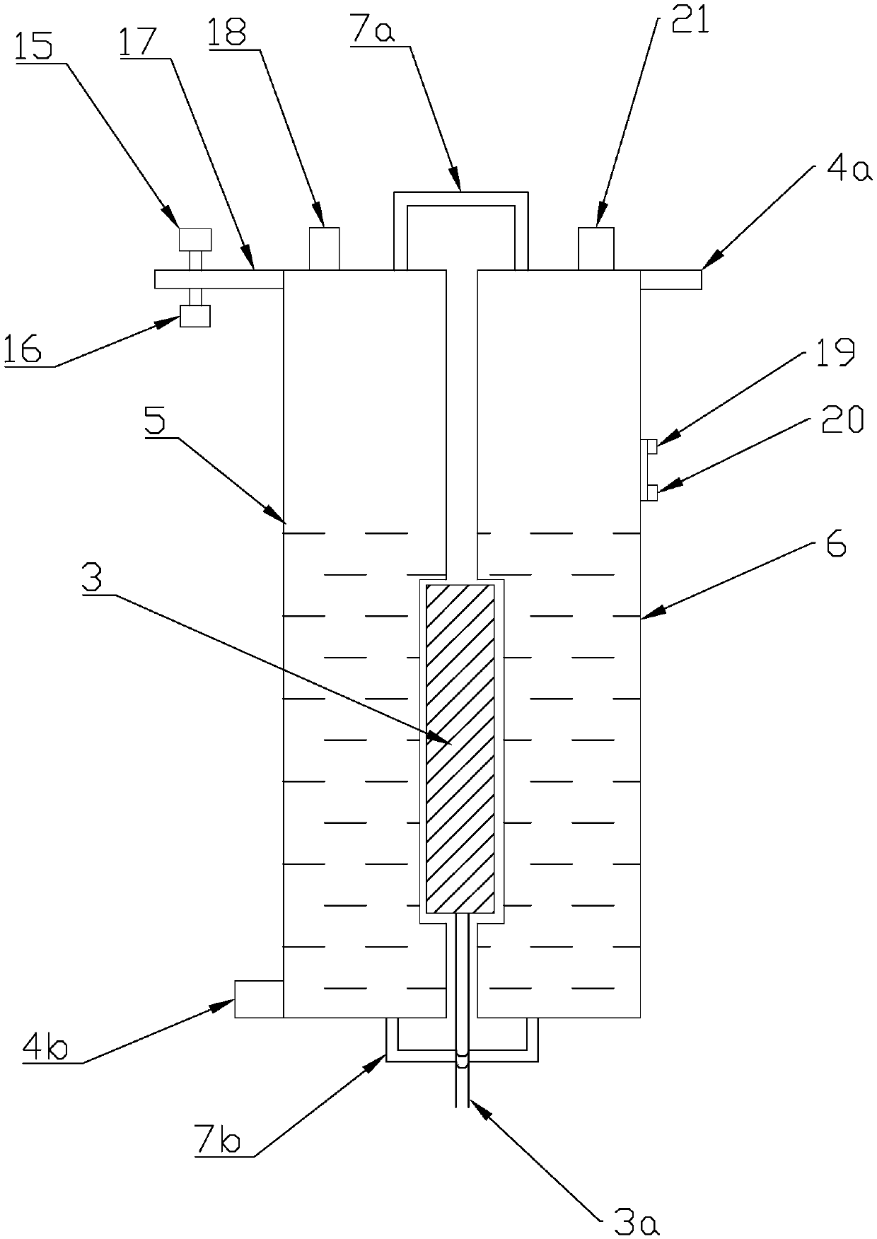
[0031] Such as figure 2 As shown, a double-sided steam generator includes a left water tank 5 and a right water tank 6 as steam generator shells, and recesses are arranged on the opposite surfaces of the left water tank 5 and the right water tank 6, and an electric heat source 3 is installed between the recesses. The electric heat source 3 can be arranged in a disc shape or a strip shape, and an aluminum plate is added between the strip-shaped electric heat source and the steam generator shell to achieve better heat transfer; the dotted line filling areas of the left water tank 5 and the right water tank 6 in the figure are In the water storage area of ​​the water storage chamber, the upper part is a steam storage chamber, and the steam storage chamber is provided with a steam outlet 17; the water storage chamber is connected through the water storage conduit 7b, and the steam storage chamber is connected through the steam conduit 7a.

Embodiment 3

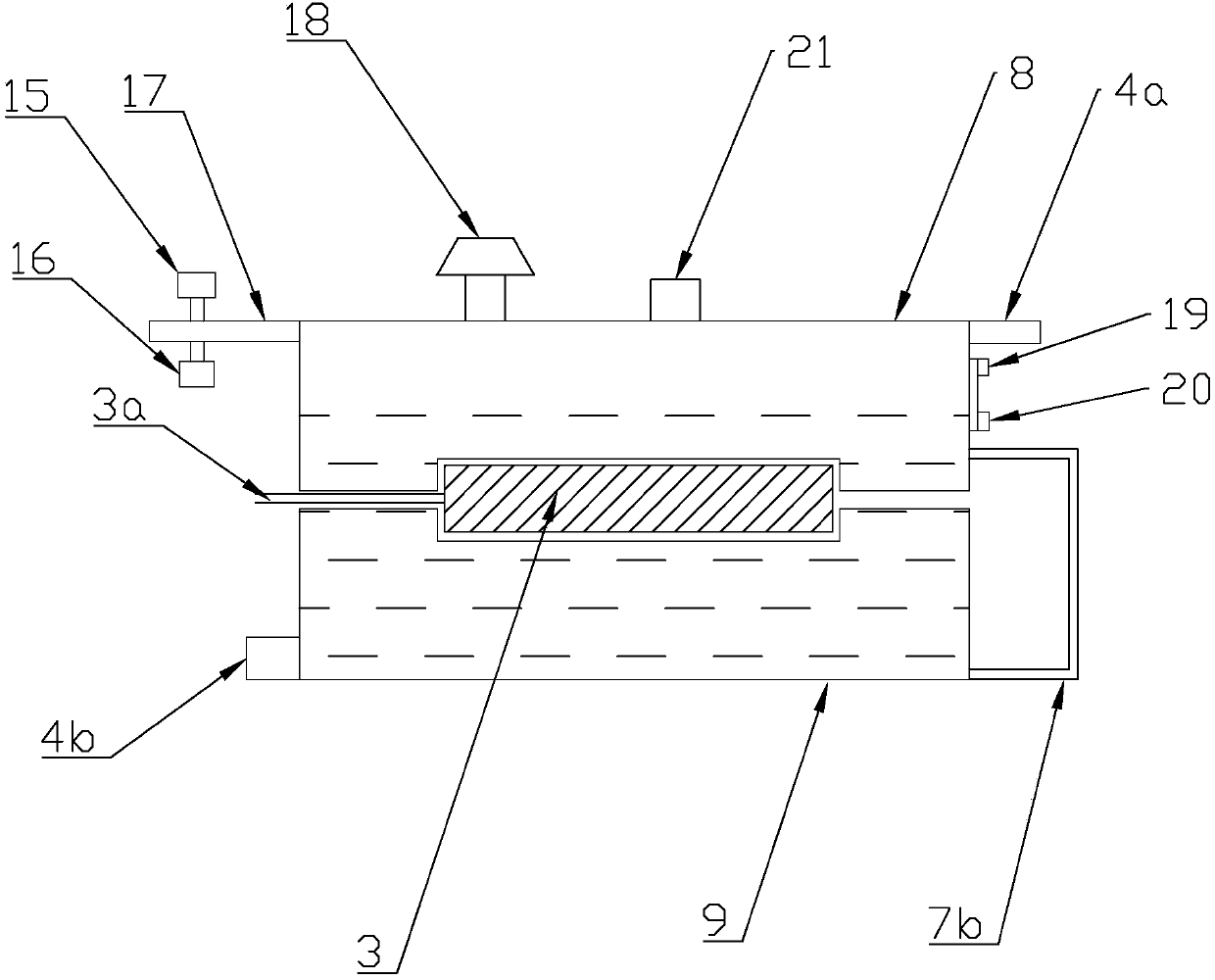
[0033] Such as image 3 As shown, a double-sided steam generator includes an upper water tank 8 and a lower water tank 9 as a steam generator housing, the opposite surfaces of the upper water tank 8 and the lower water tank 9 are concave, and an electric heat source 3 is installed between the concave surfaces. The electric heat source 3 can be arranged in a disc shape or a strip shape, and an aluminum plate is added between the strip-shaped electric heat source and the steam generator shell to achieve better heat transfer; Water cavity, the upper part of the upper water tank 8 is a steam storage cavity, and the water storage cavity is communicated by a water storage conduit.


PUM


Abstract

The invention relates to a double-sided heating steam generator, which comprises an electrical heat source and a steam generator shell, the electrical heat source is provided with two heating surfaces which are opposite from each other, the steam generator shell is provided with two opposite heated surfaces, and the electrical heat source is located between the two heated surfaces. The double-sided heating steam generator provided by the invention adopts the double-sided heating principle to increase thermal efficiency.

Description

technical field [0001] The invention belongs to the field of ironing equipment, in particular to a double-sided heating steam generator, a steam generating device and a steam ironing machine. Background technique [0002] The steam generators on the existing market are all heated on one side, and the heating efficiency is low, and the power consumption is large, and the economic burden of electricity charges for ironing clothes in families and clothing stores is large. Contents of the invention [0003] One of the objectives of the present invention is to provide a double-sided heating steam generator, which adopts the principle of double-sided heating to improve thermal efficiency. [0004] The purpose of the present invention is achieved like this: [0005] A double-sided heating steam generator, including an electric heat source and a steam generator casing, inside the steam generator casing there is a steam storage chamber and a water storage chamber, the steam storag...

Claims


Application Information

Patent Timeline
Patent Type & Authority Patents(China)
IPC IPC(8): F22B1/28F22B35/00F22B37/44F22B37/46F22B37/47F22D5/26
CPCF22B1/28F22B35/00F22B37/446F22B37/46F22B37/47F22D5/26
Inventor 邵博言
Owner 邵博言
Why Eureka
Try Eureka