Cooling component and oil heater warmer

A technology for heaters and components, which is applied to central heating components, household heating, space heating and ventilation details, etc. It can solve the problem of temperature rise at the end of oil heater heaters, achieve simple welding methods, and avoid excessive temperature rise , the effect of easy operation

Active Publication Date: 2017-01-04
SHIJIAZHUANG GREE SMALL HOUSEHOLD ELECTRICAL APPLIANCES +1
View PDF4 Cites 1 Cited by
  • Summary
  • Abstract
  • Description
  • Claims
  • Application Information

AI Technical Summary

Problems solved by technology

[0003] In view of this, it is really necessary to provide a cooling component and an oil heater with a simple structure that can solve the problem of temperature rise at the tail of the oil heater.

Method used


Image

  • Cooling component and oil heater warmer
  • Cooling component and oil heater warmer
  • Cooling component and oil heater warmer

Examples


Embodiment Construction

[0015] The cooling member and the oil heater of the embodiment of the present invention will be described in detail below with reference to the accompanying drawings.

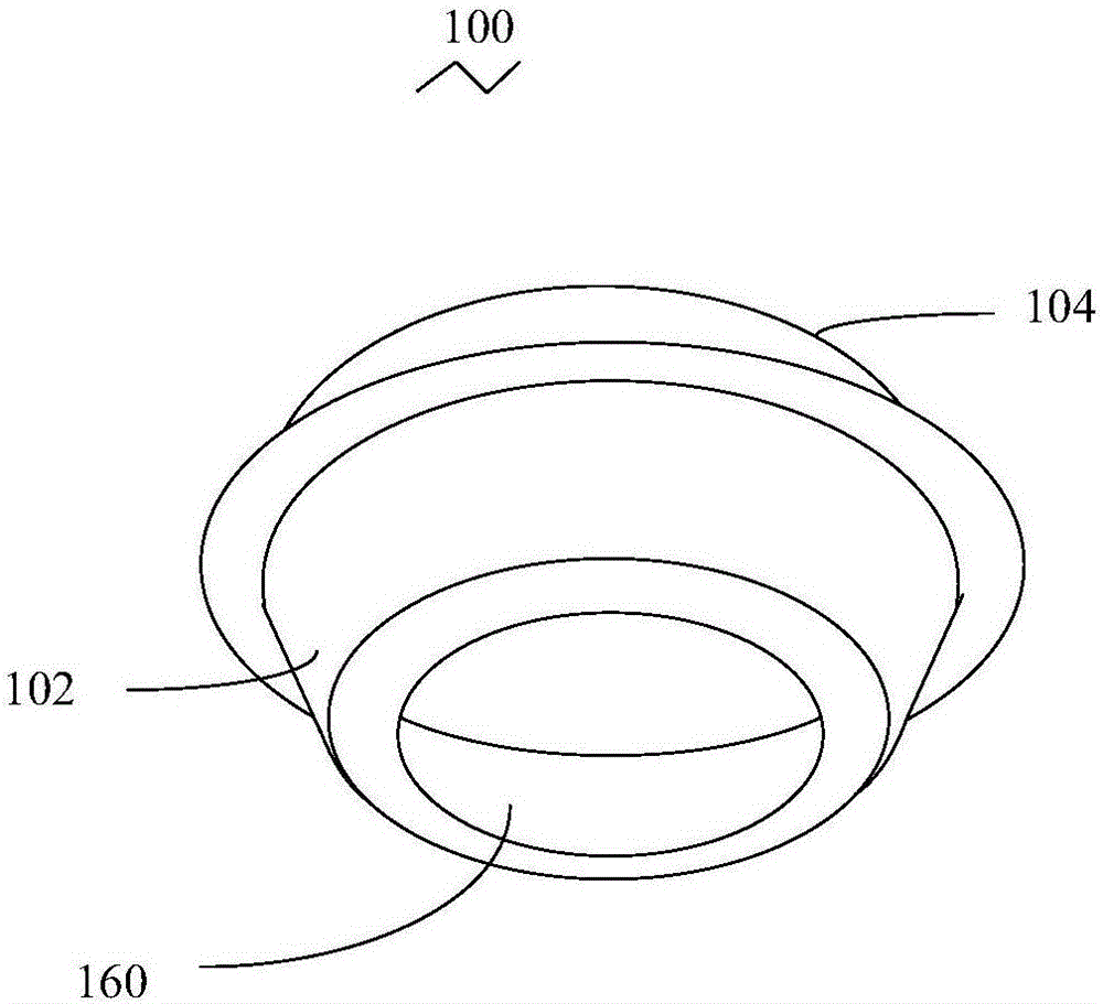
[0016] see figure 1 , the embodiment of the present invention provides a cooling member 100 for installation inside the oil heater 10, the cooling member 100 is a sealed shell structure, the cooling member 100 includes a front end and a rear end opposite to the front end, the cooling A cavity for accommodating heat transfer oil is defined inside the component 100 , and a first opening 160 is further opened at the front end of the cooling component 100 .

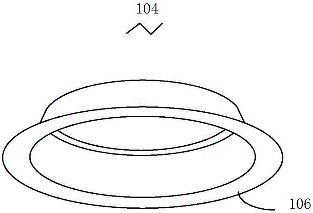
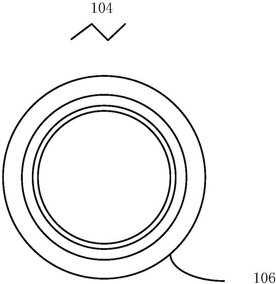
[0017] The material of the cooling component 100 can be metal or alloy. see Figure 2 to Figure 5 , in a preferred embodiment, the front end and the rear end of the cooling member 100 are the front piece 102 and the back piece 104 respectively, the front piece 102 and the back piece 104 are both bowl-shaped, and have the same bowl mouth, the front piece Bow...


PUM


Abstract

The invention relates to a cooling component. The cooling component is of a sealed shell structure and comprises a front end and a rear end, a cavity used for containing heat conduction oil is defined in the cooling component, and a first open hole is further formed in the front end of the cooling component. The invention further relates to an oil heater warmer. The oil heater warmer comprises a plurality of cooling units and the cooling component, the cooling component is arranged in an upper convex hull unit and a lower convex hull unit of the last cooling unit, and the front end of the cooling component faces the front end of the oil heater warmer; the front end of the cooling component is in sealed connection with the corresponding upper convex hull unit and the corresponding lower convex hull unit. The last cooling unit of the oil heater warmer is isolated from the heat conduction oil.

Description

technical field [0001] The invention relates to the field of household appliances, in particular to a cooling component and an oil heater. Background technique [0002] Electric oil heater, also known as oil-filled heater, is a safe and reliable space heater. It is mainly composed of electric heating tube, heat sink, temperature control element, power switch, indicator light and so on. The electric heating tube is installed inside the cavity of the heat sink, and heat conduction oil is injected around the electric heating tube in the cavity. When the power is turned on, the heat transfer oil around the electric heating tube is heated and rises to the upper part of the cavity, convectively circulates in the heat sink, and radiates heat through the surface of the heat sink, thereby heating the space environment. The heat transfer oil cooled by the air descends to the electric heating tube and is heated again to start a new cycle. In order to reduce the temperature at the en...

Claims


Application Information

Patent Timeline
Patent Type & Authority Applications(China)
IPC IPC(8): F24D13/04F24D19/00F24D19/10
CPCF24D13/04F24D19/00F24D19/1096F24D2200/08F24D2220/2009
Inventor 贾东
Owner SHIJIAZHUANG GREE SMALL HOUSEHOLD ELECTRICAL APPLIANCES
Why Eureka
Try Eureka