Hydraulic cylinder piston rod welding structure

A welding structure and piston rod technology, which is applied in the field of hydraulic cylinders, can solve problems such as narrow gaps and failure to meet design requirements, and achieve the effects of reducing welding requirements, good positioning, and improving stability

Inactive Publication Date: 2018-03-02
XUZHOU YONGJIA HYDRAULIC EQUIP
View PDF0 Cites 0 Cited by
  • Summary
  • Abstract
  • Description
  • Claims
  • Application Information

AI Technical Summary

Problems solved by technology

However, due to the limitations of its welding process, the gap between such V-shaped cuts is narrow, so the root of the welding base metal will not be penetrated, that is, the solder cannot fully fill the gap between the piston rod and the rod end. gap
This process cannot meet the design requirements at all under the condition of high pressure or high requirements on the service life of the oil cylinder.

Method used


Image

  • Hydraulic cylinder piston rod welding structure
  • Hydraulic cylinder piston rod welding structure
  • Hydraulic cylinder piston rod welding structure

Examples


Embodiment Construction

[0017] The following is a specific embodiment of the present invention, and the present invention will be further described in conjunction with the accompanying drawings.

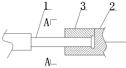
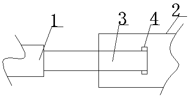
[0018] Such as Figure 1 to Figure 3 As shown, a hydraulic cylinder piston rod welding structure includes a rod body 1 and a rod end 2;

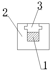
[0019] recombine Figure 4 As shown, there is a square extension rod 1-1 at the right end of the rod body 1, and a square positioning block 1-2 is fixed on the right end of the extension rod 1-1; the extension rod 1-1 extends around the positioning block 1-2. the end of.

[0020] in combination Figure 5 As shown, the rod end 2 has a chute 2-1; the chute 2-1 connects the left side and the upper side of the rod end 2; -3 communicates with the upper side of the rod end 2; the extension rod 1-1 of the rod body 1 slides into the bottom of the chute 2-1 from the upper side of the rod end 2, and the positioning block 1-2 of the rod body 1 slides from the upper side of the r...


PUM


Abstract

The invention discloses a hydraulic cylinder piston rod welding structure, which belongs to the technical field of hydraulic cylinders. It includes a rod body, a rod end and a clamp block; the extension rod of the rod body slides into the bottom of the chute from the upper side of the rod end, and the positioning block of the rod body slides into the bottom of the positioning groove from the upper side of the rod end; the clamp The block slides into the bottom of the chute from the left end of the bar end, and the block is pressed on the upper side of the extension bar and the positioning block, and meanwhile, the protruding bar on the block slides into the draw-in groove of the bar end. In the welding structure of the present invention, the extension rod and the positioning block in the rod body only have a tendency to move upward; the block is pressed on the extension rod and the positioning block, and the block itself only has a tendency to move to the left. The block has a good positioning effect; since the block itself is only subjected to an upward force and no force to the left, the requirements for the welding of the block are very low, and the requirements for the welding structure of the fixed whole are very low.

Description

technical field [0001] The invention relates to the technical field of hydraulic cylinders, in particular to a hydraulic cylinder piston rod welding structure. Background technique [0002] At present, the production process of the piston rod of the hydraulic cylinder is mostly butt welding between the piston rod and the rod end. When the two are spliced, the chamfer forms a V shape. However, due to the special shape of the V-shaped welding joint, spot welding is generally used to position the piston rod and the rod end when welding the piston rod and the rod end, and then the full welding process is performed manually. This manual welding process can basically meet the needs of use when the force on the rod end of the piston rod is not large. However, due to the limitations of its welding process, the gap between such V-shaped cuts is narrow, so the root of the welding base metal will not be penetrated, that is, the solder cannot fully fill the gap between the piston rod ...

Claims


Application Information

Patent Timeline
Patent Type & Authority Applications(China)
IPC IPC(8): F15B15/14
CPCF15B15/1457
Inventor 王世永
Owner XUZHOU YONGJIA HYDRAULIC EQUIP
Why Eureka
Try Eureka