
High-temperature containment test technology for aeroengine casing

A high temperature and casing technology, applied in the field of high temperature containment test of aero-engine casing, can solve the problems of easy damage, increased test difficulty, low strength of electric furnace materials, etc., and achieves the effect of strong flexibility and improved reference.

Active Publication Date: 2017-01-04
ZHEJIANG HIRO AVIATION TECH CO LTD
View PDF5 Cites 15 Cited by
  • Summary
  • Abstract
  • Description
  • Claims
  • Application Information

AI Technical Summary

Problems solved by technology

However, this equivalent method has certain limitations: the accuracy of the calculation formula used in the equivalent calculation of the casing containment factor and its applicability to specific casing components cannot be guaranteed
This method can realize the containment test of the casing under high temperature conditions, but because the shape of the electric furnace is regular and the furnace wall is thick, it needs to occupy a large space, which increases the size requirements of the tester and increases the difficulty of the test
In addition, since the heating furnace fully enclosed the test piece, the high-speed recorder could not be used to photograph the impact process of the flying blade and the casing during the test.
Furthermore, due to the low strength of the electric furnace material, it is easily damaged by the impact of the failed rotor in the high-speed rotation test, and the reuse rate is low, resulting in an increase in the test cost

Method used


Image

  • High-temperature containment test technology for aeroengine casing
  • High-temperature containment test technology for aeroengine casing
  • High-temperature containment test technology for aeroengine casing

Examples


Embodiment Construction

[0028] The present invention will be further described below in conjunction with the accompanying drawings and examples.

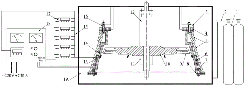
[0029] Such as figure 1 As shown, a casing high-temperature containment test device based on a contact heating method includes a contact electric heater 6, a thermocouple 13, a heating wire and a thermocouple lead wire 15, a temperature control cabinet 18, an upper heat shield 4, a lower partition Hot plate 8, thermal insulation blanket 5, temperature display instrument 17, etc.

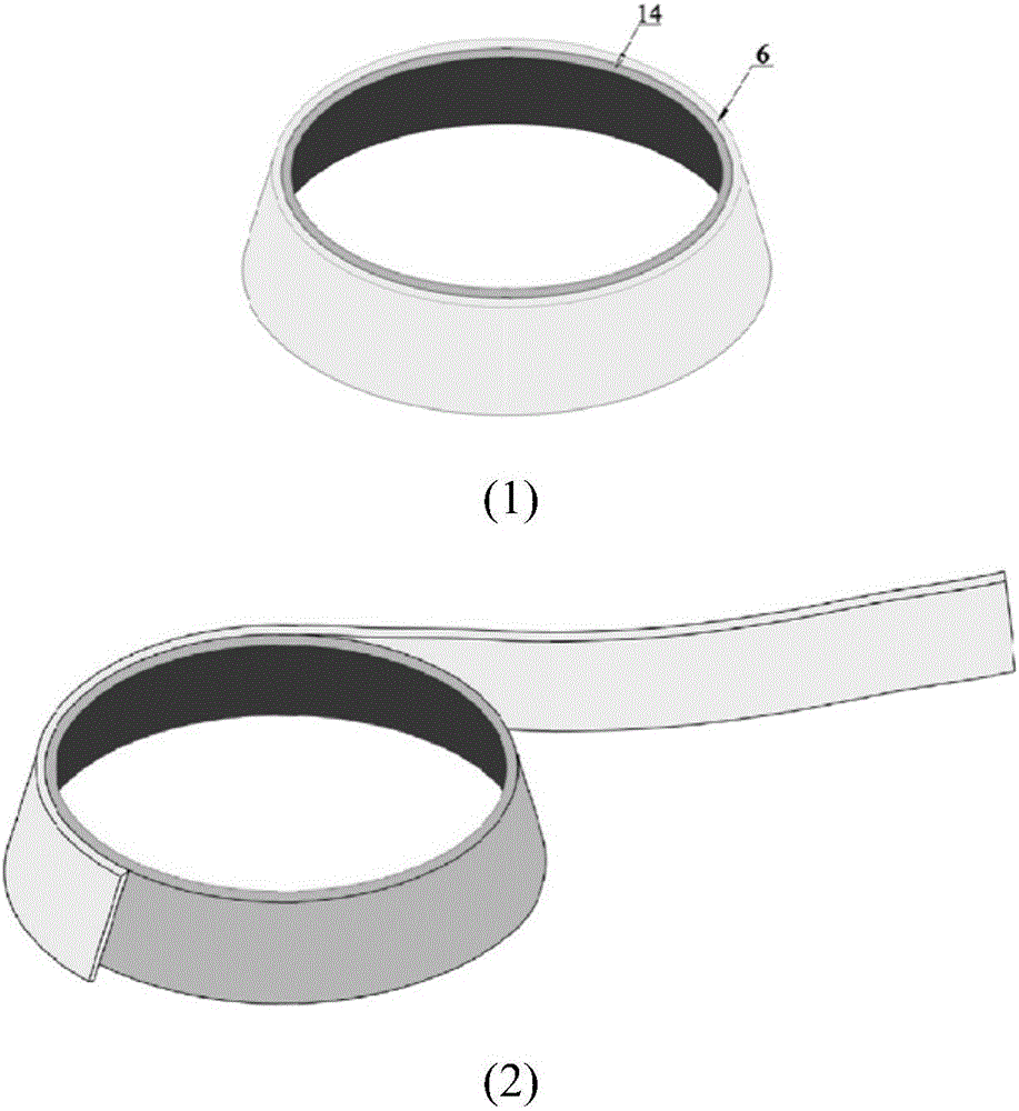
[0030] The case 14 acts as the main body for heating, and the outer wall is wound by the contact electric heater 6 for a circle, and the contact electric heater 6 is connected end to end; the upper heat shield 4 and the lower heat shield 8 are respectively located on the upper and lower installation sides of the case 14 and connected position; thermal insulation felt 5 is wound outside the contact electric heater 6 and according to the thermal insulation requirements and the act...


PUM


Abstract

The invention discloses a high-temperature containment test technology for an aeroengine casing. A soft wall high temperature contact-type electric heater is wound on the outer wall of the casing, the outer part of the heater is coated with an insulation quilt, thermal baffles are cushioned at an upper mounting edge and a lower mounting edge of the casing, and the insulation quilt and the thermal baffles enable the heater and the casing to be in relatively-closed space. A power line of the heater is connected with a thermocouple attached to the inner wall of the casing and a temperature control box, and the thermocouple measurement result serves as a temperature feedback to enable the heating power to be adjusted automatically. The rest thermocouples are connected with temperature display instruments to observe uniformity of circumferential heating of the casing. The testing device and the testing technology method provided by the invention are mainly applied to the aeroengine casing high-temperature containment test, and the casing containment ability is checked in a condition closer to the working condition of the engine. The casing high-temperature containment test device comprises the soft wall contact-type electric heater, the heating power line, the thermal baffles, the insulation quilt, the thermocouples, thermocouple leads, the temperature control box, the temperature display instruments and the like.

Description

technical field [0001] The invention relates to a high-temperature containment test technology for an aero-engine case, including a case high-temperature containment test device and test method based on a contact heating method. The invention uses a soft-wall contact electric heater and its measurement and control system to realize machine The temperature of the casing is precisely and controllable, and it is used for the high-temperature containment test of the aero-engine casing. Background technique [0002] The high-speed rotating components of aero-engines and auxiliary power units work under extreme loads and harsh environments for a long time. Due to the impact of foreign objects, high-cycle fatigue, overheating and material defects, it is inevitable that high-speed rotating blades will break and damage accidents. The high-speed and high-energy dangerous fragments fly out through the casing, which will damage the aircraft cabin, fuel tank, hydraulic pipeline and elect...

Claims


Application Information

Patent Timeline
IPC IPC(8): G01M13/00
CPCG01M13/00
Inventor 宣海军白聪儿邹煜申瞿明敏何泽侃黄先念
Owner ZHEJIANG HIRO AVIATION TECH CO LTD
Learn More