Scene light source estimation accuracy improving method based on camera response function

A camera response and light source technology, which is applied in the fields of computer vision and image processing, can solve problems such as the inability to effectively improve the accuracy of light source estimation, and achieve the effect of improving accuracy

Active Publication Date: 2017-01-04
UNIV OF ELECTRONICS SCI & TECH OF CHINA
View PDF3 Cites 6 Cited by
  • Summary
  • Abstract
  • Description
  • Claims
  • Application Information

AI Technical Summary

Problems solved by technology

[0004] The purpose of the present invention is to solve the problem that the learning-based method in the prior art cannot effectively improve the accuracy of light source estimation between different cameras, and proposes a method for improving the accuracy of scene light source estimation based on camera response functions

Method used


Image

  • Scene light source estimation accuracy improving method based on camera response function
  • Scene light source estimation accuracy improving method based on camera response function
  • Scene light source estimation accuracy improving method based on camera response function

Examples


Embodiment 1

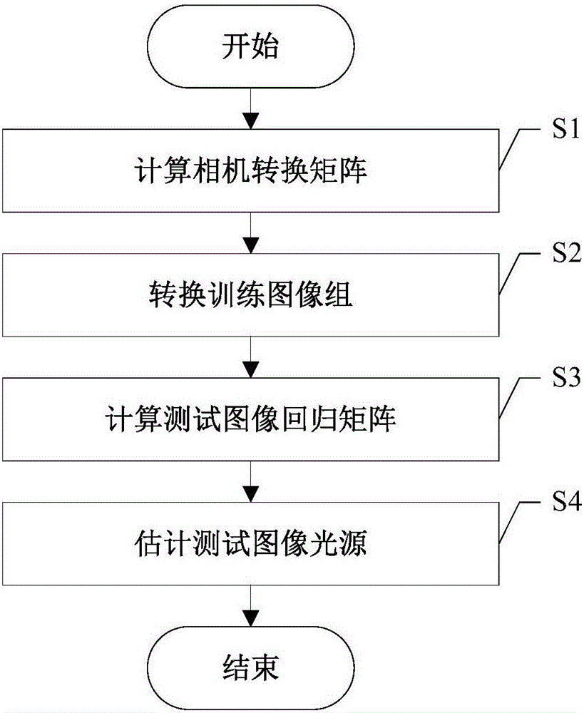
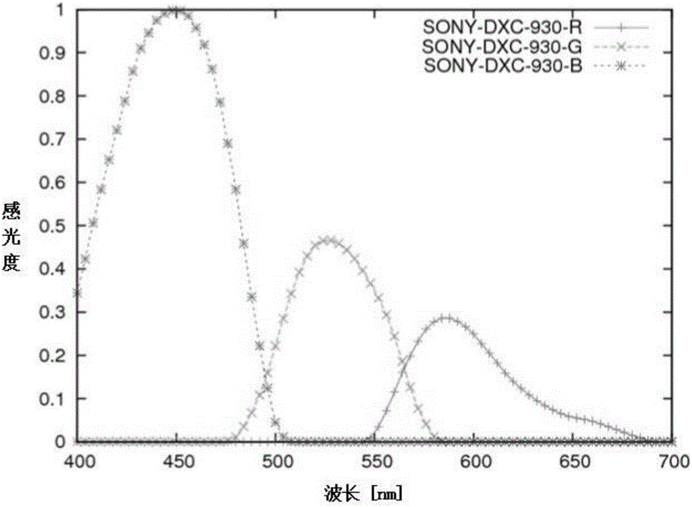
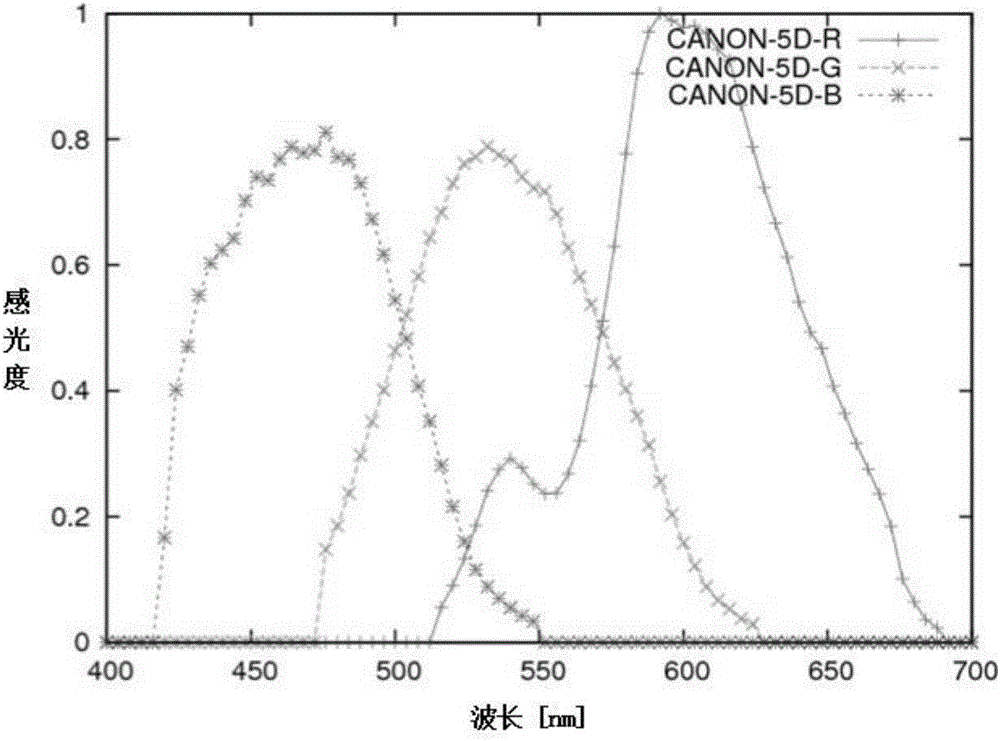
[0031] Download the artificially synthesized surface S from the currently internationally recognized image library website for estimating the color of the scene light source, and download the 321 color shift images T and its real light source L taken by the image library with the SONY DXC 930 camera as the training set. At the same time, download another image library, an image IMG_0332.png taken by a CANON 5D camera, as a test image, and the image size is 1460*2193. Neither the training set images nor the test images have undergone any camera preprocessing (such as white balance, gamma value correction). Then the detailed steps of the present invention are as follows:

[0032] S1. Calculating the camera conversion matrix: Calculate the color sensitivity response function of the camera (SONY DXC930) used in the training image to the color sensitivity response function of the camera (CANON 5D) used in the test image to the same given surface reflectance by the least square meth...

Embodiment 2

[0071] The pixel values ​​of each color component of the original input image are respectively corrected by using the light source color values ​​under each color component calculated in step S4. Taking a pixel value (0.459, 0.545, 0.472) of the test image input in the step S4 as example, the corrected result is (0.459 / 0.3765, 0.545 / 0.3435, 0.472 / 0.2800)=(1.2191, 1.5866, 1.6857), and then Multiply the corrected value by the standard white light factor Obtain (0.7038, 0.9160, 0.9732) as the pixel value of the final output corrected image, do similar calculations for other pixel values ​​of the original input image, and finally obtain the corrected color image.

[0072] Such as Figure 4 Shown is the original image to be corrected, and the image after performing tone correction on the light source color value calculated by step S4 is as follows Figure 5 shown.


PUM


Abstract

The invention discloses a scene light source estimation accuracy improving method based on a camera response function. The method comprises the steps of calculating out a camera transfer matrix between a training image and a test image at first; then utilizing the matrix to convert the training image and a true light source of the training image into an image and a true light source under a camera which correspond to the test image; extracting characteristics of the converted image; learning a regression matrix between the characteristics and the true light source; finally utilizing the regression matrix to finish light source estimation of the test image and achieving the light source estimation between different image libraries. According to the method, any parameter is avoided, the transfer matrix between the cameras and the regression matrix between the characteristics of the training image and the light source can be determined by being calculated out once and can be directly applied to estimating light sources of images shot by the cameras used by the different training images, and the light source estimation accuracy between the different cameras can be effectively improved.

Description

technical field [0001] The invention belongs to the technical field of computer vision and image processing, and in particular relates to the design of a method for improving the accuracy of scene light source estimation based on a camera response function. Background technique [0002] Color constancy refers to the perceptual characteristic that people's perception of the color of the object's surface remains unchanged when the color of the light source illuminating the surface of the object changes. one ability. Color constancy calculation methods mainly include learning-based algorithms and static methods. Static methods are difficult to meet engineering needs in terms of accuracy due to large estimation errors. Learning-based algorithms can obtain more accurate light source estimates by learning complex image features. At present, learning-based algorithms cannot be applied and promoted. In addition to the relatively large amount of calculation, another important reason...

Claims


Application Information

Patent Timeline
Patent Type & Authority Applications(China)
IPC IPC(8): G06T7/00H04N5/235
CPCH04N23/71
Inventor 李永杰高绍兵张明罗福亚
Owner UNIV OF ELECTRONICS SCI & TECH OF CHINA
Why Eureka
Try Eureka