Calibration board, camera calibration method and device

A technology for calibrating boards and cameras, applied in image enhancement, image analysis, image data processing, etc., can solve problems such as low calibration accuracy, and achieve the effect of improving calibration speed, user experience, and speed.

Pending Publication Date: 2017-01-04
上海商泰汽车信息系统有限公司
View PDF0 Cites 6 Cited by
  • Summary
  • Abstract
  • Description
  • Claims
  • Application Information

AI Technical Summary

Problems solved by technology

[0004] However, in the prior art, when calibrating the external parameters of the vehicle-mounted camera, there is a problem of low calibration accuracy

Method used


Image

  • Calibration board, camera calibration method and device
  • Calibration board, camera calibration method and device
  • Calibration board, camera calibration method and device

Examples


Embodiment Construction

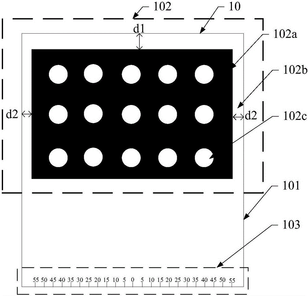
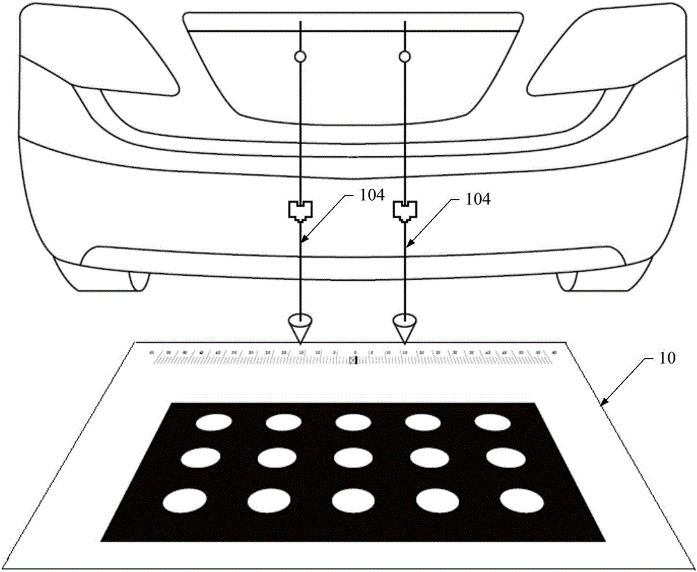
[0027] In order to solve the above problems, in the embodiment of the present invention, by setting the positioning area on the calibration plate, the calibration plate can be placed in a preset position directly behind the vehicle, that is, within the field of view of the vehicle-mounted camera, so that the vehicle-mounted camera can accurately shoot. The image of the calibration plate is obtained, so that the external parameters of the vehicle-mounted camera can be accurately calibrated based on the captured calibration image, thereby improving the calibration accuracy of the vehicle-mounted camera.

[0028] In order to make the above objects, features and beneficial effects of the present invention more clearly understood, specific embodiments of the present invention will be described in detail below with reference to the accompanying drawings.

[0029] figure 1 A schematic structural diagram of a calibration plate in an embodiment of the present invention is shown. see ...


PUM


Abstract

The invention relates to a calibration board, a camera calibration method and a device. The calibration board comprises a calibration substrate, wherein an upper surface of the calibration substrate is provided with a calibration region and a positioning region, the calibration region is suitable for calibrating outer parameters of a vehicle-mounted camera, and the positioning region is suitable for determining a placement position of the calibration board in a view field of the vehicle-mounted camera. The calibration board is advantaged in that calibration accuracy of the vehicle-mounted camera can be improved.

Description

technical field [0001] The invention relates to the technical field of automotive electronics, in particular to a calibration board, a camera calibration method and a device. Background technique [0002] Calibration Target can be used to correct the lens distortion of the camera in applications such as machine vision, image measurement, photogrammetry, and 3D reconstruction. [0003] In the prior art, the plane calibration board has been widely used in the parameter calibration of the camera because of its good portability. Using a plane calibration plate to calibrate the camera parameters, that is, through the relationship between the three-dimensional geometric position of the preset point on the surface of the calibration plate and the position of the corresponding point in the image, the corresponding imaging geometric model is established, so as to obtain high precision. measurement and reconstruction results. [0004] However, in the prior art, when calibrating the ...

Claims


Application Information

Patent Timeline
IPC IPC(8): G06T7/00
CPCG06T2207/10016
Inventor 余良德房宏康毛辉杰任亮亮孙志成
Owner 上海商泰汽车信息系统有限公司
Why Eureka
Try Eureka