

Storage cabinet control system and method
A control system and locker technology, applied in the field of lockers, can solve the problem of not being able to store items of various sizes and specifications, and achieve the effect of improving convenience and storage space
Inactive Publication Date: 2017-01-04
柳州市旭邦科技有限公司
View PDF4 Cites 10 Cited by
- Summary
- Abstract
- Description
- Claims
- Application Information
AI Technical Summary
Problems solved by technology
This solution can only store items of one size and specification, but cannot store items of multiple sizes and specifications, so it is necessary to solve this problem
Method used
View moreImage
Smart ImageViewing Examples

Examples
Embodiment 2
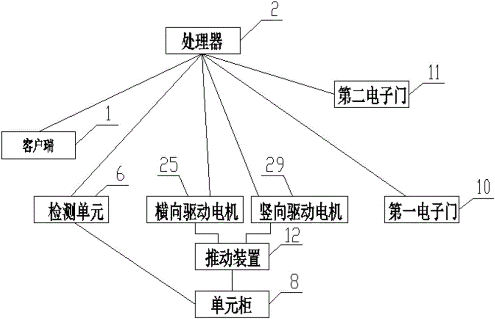
[0054] like Figure 5 As shown, a locker control method includes the following steps:
[0055] Touch or press the client 1 to generate a control signal; the processor 2 performs signal processing on the control signal to generate a driving signal;
[0056] The locker 3 pushes a plurality of vacant unit cabinets 8 inside it according to the drive signal to perform combination adjustment;
Login to View More PUM
 Abstract
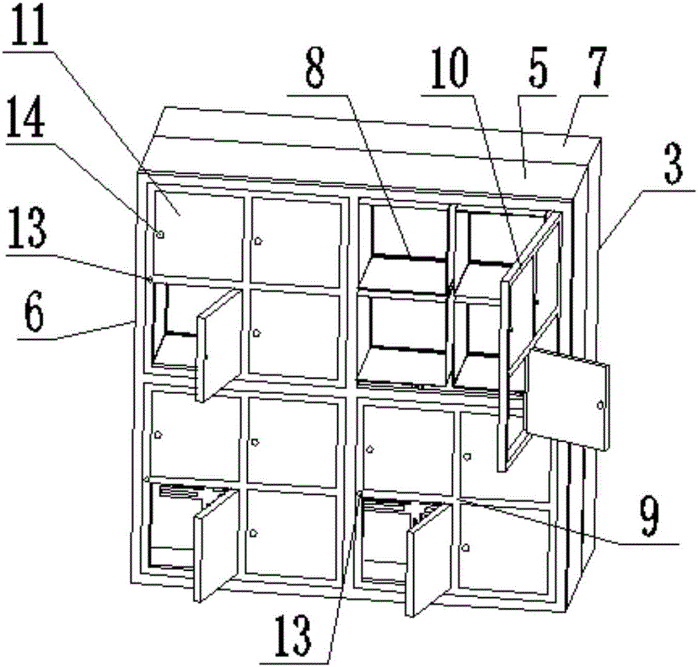
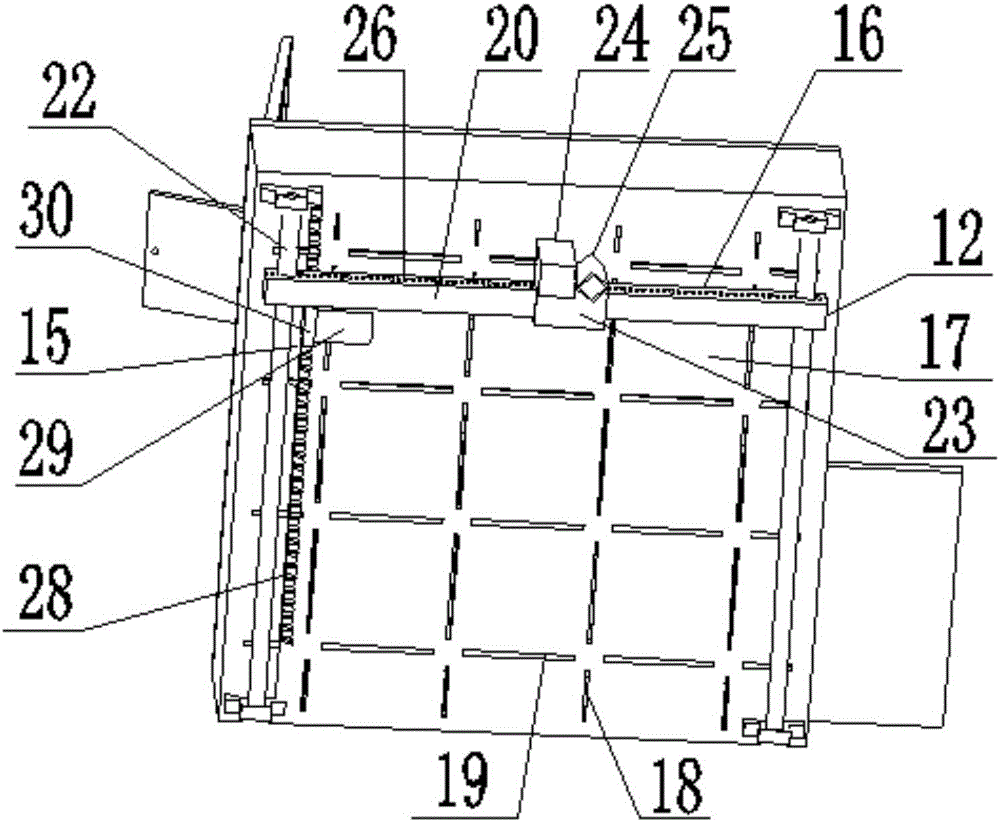
The invention relates to a storage cabinet control system and method. The system comprises a client side, a processor, a storage cabinet and a detecting unit. The client side is connected with the processor and used for generating a control signal according to touching or pressing; the processor is connected with the storage cabinet, used for processing the control signal to generate a driving signal and further used for carrying out signal processing on an in-place adjusting signal to generate a door opening signal; the storage cabinet is used for pushing a plurality of empty unit cabinets in the storage cabinet to be assembled and adjusted according to the driving signal and further used for opening the multiple unit cabinets according to the door opening signal; the detecting unit is arranged in the storage cabinet, connected with the processor and used for detecting the assembling and adjusting condition of the unit cabinets, and if the unit cabinets are adjusted in place, the in-place adjusting signal is generated. A pushing device can be automatically controlled to move the internal unit cabinets, empty unit cabinet bodies are pushed together to form a cabinet body, and side plates of the unit cabinet bodies are folded to form a larger storage space.
Description
technical field [0001] The invention relates to the technical field of lockers, in particular to a locker control system and method. Background technique [0002] In the prior art, the invention with the application number 201510592687.7 relates to the technical field of smart appliances, which solves the technical problem of wasting space occupied by smart lockers in the prior art, by providing an intelligent rotating locker, including a cylindrical cabinet , a rotating shaft passing through the central axis of the cylindrical cabinet, an electronic combination lock, and a position detection device. The cylindrical cabinet includes a plurality of storage cabinets arranged around the cylindrical wall, each storage cabinet is provided with a cabinet door, and the electronic combination lock controls each The switch of the cabinet door provided by the storage cabinet, the position detection device is arranged on the rotating shaft, and is connected with an electronic combinati...
Claims
Login to View More Application Information
Patent Timeline
 Patent Type & AuthorityApplications(China)
IPC IPC(8): G07F17/12G07C9/00A47B81/00G05B19/04
CPCG07F17/12A47B81/00G05B19/04G07C9/00174G07C9/00896
Inventor刘上连蒋宗跃
Owner柳州市旭邦科技有限公司