
Filter capacitor fixing device

A technology for fixing devices and filter capacitors, which is applied in the direction of capacitors and electrical components, and can solve problems such as space position restrictions

Active Publication Date: 2017-01-04
CRRC YONGJI ELECTRIC CO LTD
View PDF2 Cites 1 Cited by
  • Summary
  • Abstract
  • Description
  • Claims
  • Application Information

AI Technical Summary

Problems solved by technology

However, when the number of capacitors connected in series or in parallel is large, and the space is limited, and the space cannot be increased at will, there is not enough space to arrange all the capacitors by using the clamping and fixing method of the angle steel bracket.

Method used


Image

  • Filter capacitor fixing device
  • Filter capacitor fixing device
  • Filter capacitor fixing device

Examples


Embodiment Construction

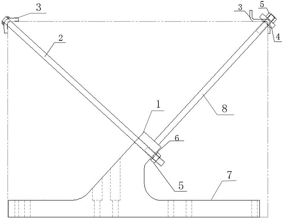
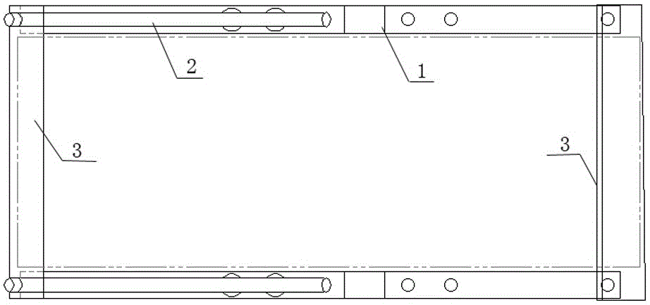
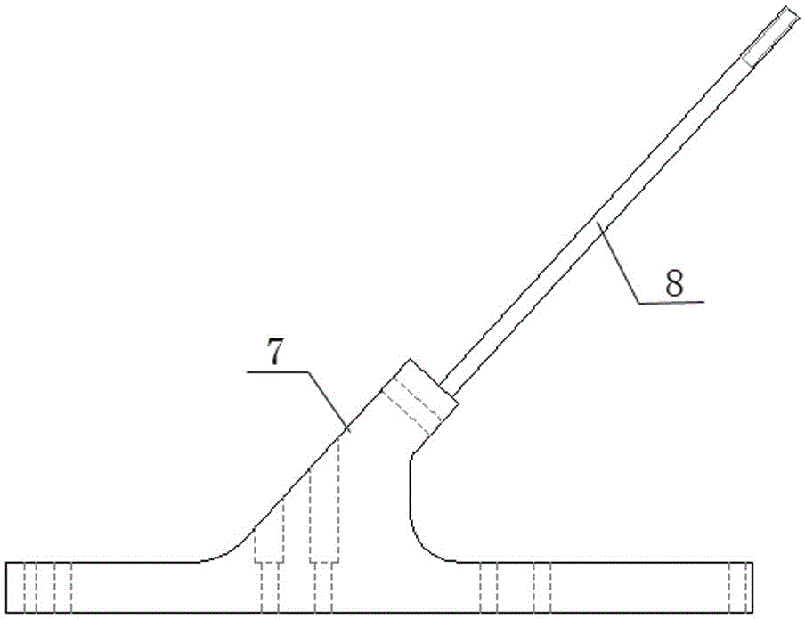
[0016] A filter capacitor fixing device, comprising a capacitor support 2 and a pair of capacitor fixing frames 1, the capacitor fixing frame 1 includes a fixing frame base 7 and an oblique pull rod 8 arranged on the fixing frame base, and the oblique pull rods on the two capacitor fixing frames The free ends of 8 are connected with a bending plate 3 that is bent at 90 degrees in the middle, and the free end of the oblique pull rod 8 is also provided with a pressing plate 4 and is pressed and fixed on the bending place of the bending plate by a nut 5. The inclination angle and length of the pull rod 8 are set according to the rectangular capacitor to be fixed, so that the free end of the oblique pull rod is located at an arc corner on the top surface of the rectangular capacitor, and the front and rear ends of the two fixed mount bases 7 A front fixing plate and a rear fixing plate are respectively connected between them. The capacitor support 2 includes two rods arranged in pa...


PUM


Abstract

The invention relates to a clamping and fixing structure of a capacitor, in particular to a filter capacitor fixing device. The filter capacitor fixing device comprises a pair of capacitor fixing frames and a capacitor supporting frame. Each capacitor fixing frame comprises a fixing frame base and an oblique pull rod arranged on the fixing frame base. A bend board with the middle bent into 90 degrees is connected between free ends of the oblique pull rods on the two capacitor fixing frames. Pressing boards are arranged at the end portions of the free ends of the oblique pull rods and fixedly pressed at the bent portion of the bend board through a nut. A front fixing board and a rear fixing board are connected between the front ends of the two fixing frame base and the rear ends of the two fixing frame base respectively. The capacitor supporting frame comprises two parallel rod bodies. The bend board with the middle bent into 90 degrees is connected between the end portions of the two rod bodies and fixed through a nut in a limit mode. The rod bodies of the capacitor supporting frame are obliquely arranged on the fixing frame base, and the oblique direction of the rod bodies is opposite to the oblique direction of the oblique pull rods. The filter capacitor fixing device has simple structure, allows a filter capacitor to be clamped and fixed conveniently, and meets structural design and performance parameter requirements of products.

Description

technical field [0001] The clamping and fixing structure of the capacitor of the present invention is specifically a filter capacitor fixing device. Background technique [0002] Capacitors are electronic components widely used in electronic equipment, and are important devices for improving power factor in power systems; in electronic circuits, they are the main components for oscillation, filtering, phase shifting, bypassing, and coupling. In particular, the filter capacitors in the traction auxiliary converters of EMUs are relatively large in volume and mass. Due to the limitation of the working environment, due to vibration, poor connection and other reasons, capacitor failures may be caused. In the lightest case, the outer skin of the capacitor is damaged and the outer shell expands. , the capacity is reduced or the capacity disappears; in severe cases, short-circuit breakdown, leakage or even shell bursting accidents will occur. This requires that the clamping and fix...

Claims


Application Information

Patent Timeline
IPC IPC(8): H01G2/02
CPCH01G2/02
Inventor 巩金明乔聪梅宋进民张平赵亚丽
Owner CRRC YONGJI ELECTRIC CO LTD
Learn More