A substrate-integrated waveguide planar end-fire circularly polarized antenna

A substrate-integrated waveguide and circularly polarized antenna technology, which is applied to antenna unit combinations, antennas, and waveguide horns with different polarization directions, can solve the problem of low gain and achieve improved inherent performance, wide operating frequency band, and high operating efficiency. buff effect

Active Publication Date: 2019-06-18
SICHUAN ZHONGCE MICROGRID TECH CO LTD
View PDF2 Cites 0 Cited by
  • Summary
  • Abstract
  • Description
  • Claims
  • Application Information

AI Technical Summary

Problems solved by technology

[0006] Designed by Wenhai Zhang (Wenhai Zhang, Wenjun Lu and Kamweng Tam, "Aplanar end-firecircularly polarized complementary antenna with beam in parallel with its plane," IEEE antennas and Propagation, vol.64, pp.1146-1152, January 2016) et al. The planar end-fire circularly polarized antenna uses the superposition of magnetic dipole and electric dipole to achieve circular polarization, but the impedance bandwidth is only 1.9%, and the gain is not high

Method used


Image

  • A substrate-integrated waveguide planar end-fire circularly polarized antenna
  • A substrate-integrated waveguide planar end-fire circularly polarized antenna
  • A substrate-integrated waveguide planar end-fire circularly polarized antenna

Examples


Embodiment 1

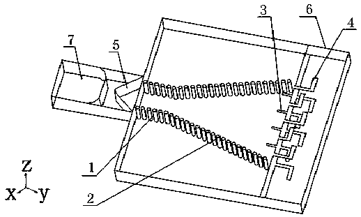
[0037] Such as Figure 1 to Figure 3 A substrate-integrated waveguide planar end-fire circularly polarized antenna is shown, including a dielectric substrate 6, a substrate-integrated waveguide, a dipole array 4, and a feed waveguide 7 connected to the dielectric substrate 6;

[0038] The substrate-integrated waveguide includes two rows of metallized via holes. The two rows of metallized via holes include straight sections parallel to each other and one end connected to the feed waveguide 7 and opening sections gradually opening to both sides along the straight section. Rows of metallized vias constitute the SIW horn structure;

[0039] The dipole array 4 includes a plurality of array elements, the array elements are located outside the opening section and connected to the upper and lower metal surfaces of the substrate integrated waveguide, and the distance between each array element and the aperture of the opening section is different. Such as figure 1 As shown, the array ...

Embodiment 2

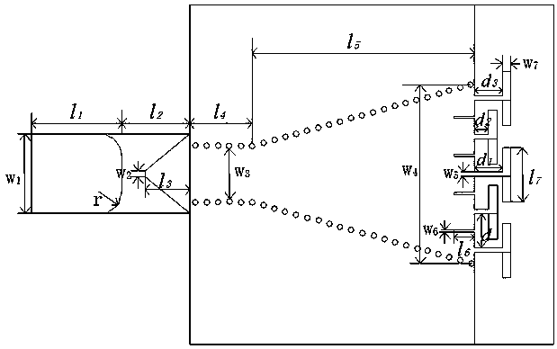
[0041] This embodiment is optimized on the basis of the above embodiments, that is, the length of the oscillator of the array element is 0.5λ-λ, and the width is 0.1λ-0.3λ, where λ is the wavelength of the electromagnetic wave in the medium at the center frequency.

[0042] The distance between two adjacent array elements of the dipole array 4 is 0.5λ-0.6λ, and the distance from the aperture of the opening section is 0.2λ-0.5λ.

[0043] Slits 3 are arranged symmetrically on the upper and lower metal surfaces of the substrate integrated waveguide, and the slits 3 are arranged at the aperture of the opening section and between two adjacent array elements. Preferably, the slot 3 is located in the middle of two adjacent array elements, and the slot width of the slot 3 is 0.03λ-0.05λ, and the slot length is 0.2λ-0.5λ.

[0044]The dielectric substrate 6 is connected with a trapezoidal tapered substrate structure 5 disposed in the cavity of the feeding waveguide 7 .

Embodiment 3

[0046] The end-fire circularly polarized antenna of the present invention is suitable for working in the millimeter wave frequency band. The superior performance of the antenna with this structure will be described below with a specific embodiment.

[0047] The medium is basically polytetrafluoroethylene F with a relative permittivity of 2.65 4 B dielectric substrate, the thickness is 3mm, the surface of the dielectric substrate is plated with copper, and the copper thickness is 0.017mm. The overall size of the antenna is 30mm wide and 32mm long.

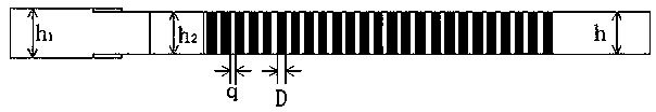
[0048] The radius of the metallized via hole is 0.3mm, the distance between two adjacent metallized via holes is 1mm, and the distance between the straight sections of two rows of metallized via holes is w 3 =5mm, the length of the straight section is l 4 = 5 mm. The thickness h of the metallized via hole determines the height of the E surface of the speaker on the H surface, the height of the E surface of the metallized via hole...


PUM


Abstract

The invention discloses a planar end-fire circular polarization antenna employing a substrate integrated waveguide. The planar end-fire circular polarization antenna comprises a dielectric substrate, the substrate integrated waveguide, a dipole array and a feed waveguide connected to the dielectric substrate, wherein the substrate integrated waveguide comprises two rows of metalized via holes; each of the two rows of metalized via holes comprises a straight section and an open section; the straight sections are parallel to one another, one end of each straight section is connected to the feed waveguide and the open sections gradually expand towards two sides along the corresponding straight sections; the substrate integrated waveguide comprises the two rows of metalized via holes; the dipole array comprises a plurality of array elements; the array elements are connected with an upper metal surface and a lower metal surface of the substrate integrated waveguide; and the spaces between the array elements and between the calibers of the open sections are different, so that the planar end-fire circular polarization antenna is low in requirements on a feed network, high in gain, simple in structure and easy to integrate, and the end-fire beam direction and the plane of the antenna are coplanar.

Description

technical field [0001] The invention relates to the field of antennas, in particular to a substrate-integrated waveguide planar end-fire circularly polarized antenna, which can be used for both receiving and transmitting radio waves. Background technique [0002] As an important transceiver device, the performance of the antenna has a great impact on the entire communication system, and the radiation form of the antenna has increasingly become an important factor in the selection of the antenna type in the wireless communication system. In many modern wireless application systems, purely linearly polarized antennas are difficult to meet the needs, and circularly polarized waves must be used for normal work. The circularly polarized antenna can receive incoming waves of any polarization, and its radiated waves can also be received by any polarized antenna, so the circularly polarized antenna can make the relative position between the transmitting antenna and the receiving ant...

Claims


Application Information

Patent Timeline
Patent Type & Authority Patents(China)
IPC IPC(8): H01Q1/36H01Q1/38H01Q13/02H01Q15/24H01Q21/24
CPCH01Q1/36H01Q1/38H01Q13/0241H01Q15/24H01Q21/24
Inventor 董宇亮蔺慧慧邓建华杜明
Owner SICHUAN ZHONGCE MICROGRID TECH CO LTD
Why Eureka
Try Eureka