UPS online hot spare switching device and method for realizing independent power supply and complete power off

A switching device and separate power supply technology, which is applied in the direction of circuit devices, electrical components, emergency power supply arrangements, etc., can solve the problems of affecting load power supply, load power supply burnout, voltage instability, etc., and reduce the risk and investment of repair or maintenance little effect

Active Publication Date: 2017-01-04
ANGANG STEEL CO LTD
View PDF4 Cites 5 Cited by
  • Summary
  • Abstract
  • Description
  • Claims
  • Application Information

AI Technical Summary

Problems solved by technology

Due to the "hot backup" connection between the two UPSs, when dealing with a faulty UPS, it may affect the normal working UPS, and in severe cases, it will affect the power supply of the load
The load using this configuration is generally an important load, and may not be able to cut off the power. When the UPS is overhauled, it can only be switched to the maintenance bypass. During this period, the load is powered by the mains. Due to the unstable voltage, it may cause the load power supply to burn out, etc. secondary accident
Since the UPS can only be switched to the maintenance bypass and cannot achieve a complete power outage, there is a problem that the UPS cannot be completely powered off for maintenance. If a complete maintenance is required, some maintenance operations must be carried out with power on or even with the load off.

Method used


Image

  • UPS online hot spare switching device and method for realizing independent power supply and complete power off

Examples


Embodiment Construction

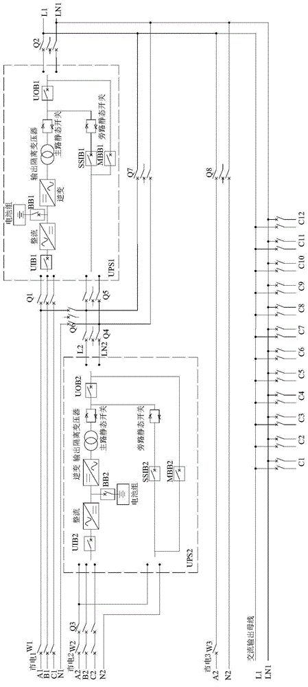
[0022] The specific embodiment of the present invention is further described below in conjunction with accompanying drawing:

[0023] Such as figure 1 As shown, mains 1 supplies power to the host UPS1 and is equipped with a low-voltage switchgear. The switch of the low-voltage switchgear is W1; 3 is the external load bypass power supply, equipped with a low-voltage switchgear, the switch of the low-voltage switchgear is W3, the mains 2 and 3 come from the same transformer, and the mains 1 and 2 come from two transformers, paralleling is not allowed run.

[0024] The input end of the host UPS1 is provided with an input switch Q1, the output end is provided with an output switch Q2 connected to the load circuit, the input end of the backup UPS2 is provided with an input switch Q3, and the output end of the backup UPS2 is connected to the static bypass input end of the host UPS1. There is also a switch Q4 and a switch Q5. The switch circuit is connected between the power supply...


PUM


Abstract

The invention relates to a UPS online hot spare backup switching device and method for realizing independent power supply and complete power off. A switching device is connected to a host computer UPS1 and a standby computer UPS2 through a line; the switching device comprises a switching circuit, a load circuit and a bypass power supply system outside the load; the host computer UPS2 and the standby computer UPS2 are powered by a higher level power supply system; the output terminal of the standby computer UPS2 is connected to a static bypass input terminal of the host computer UPS1 through two switching switches; the switching circuit is connected between a power supply circuit and a load circuit of the host computer UPS1 and is intersected with a connection circuit of the host computer UPS1 and the standby computer UPS2; switching switches are respectively arranged in front of and behind an intersection point; the switching is only allowed when the two UPSs are in a bypass output state; and when the two UPSs are in inverter output or one UPS is in the inverter output and the other one is in bypass output, the switching is not allowed. The UPS online hot spare backup switching device and method require less investment, can perform reasonable switching in the premise of improving stability and reliability of the UPS output power supply, provide regular maintenance to the UPS, and provide a solution to a fact that the power supply to the load device is not affected during outrage failure of one or two UPS devices.

Description

technical field [0001] The invention relates to the field of electrical equipment, in particular to a UPS online hot backup switching device and a switching method for realizing separate power supply and complete power failure. Background technique [0002] UPS online hot backup uses the inverter output of one UPS as the backup of the static bypass input of another UPS, that is, if the main UPS fails, the static switch will transfer the load to the inverter output circuit of the standby UPS, not only The power supply will not be interrupted, and the UPS output power supply voltage is guaranteed to be the inverter output voltage. Therefore, this configuration can effectively improve the stability and reliability of the load power supplied by the UPS. With this configuration, if the main UPS or backup UPS fails and needs to be repaired, it cannot be switched to another normal UPS to supply power to the load alone. Since there is a "hot backup" connection between the two UPSs...

Claims


Application Information

Patent Timeline
Patent Type & Authority Applications(China)
IPC IPC(8): H02J9/06
CPCY02B70/30Y04S20/20
Inventor 尚德良马永东艾立军关长生刘绍清
Owner ANGANG STEEL CO LTD
Why Eureka
Try Eureka