Method for looking for middle position of motor

A technology of motors and predetermined directions, which can be used in televisions, electrical components, image communications, etc., and can solve problems such as differences

Active Publication Date: 2017-01-04
NINGBO SUNNY OPOTECH CO LTD
View PDF5 Cites 1 Cited by
  • Summary
  • Abstract
  • Description
  • Claims
  • Application Information

AI Technical Summary

Problems solved by technology

[0005] One object of the present invention is to provide a method for finding the middle position of the motor, using software to automatically find the middle position through images, solving the problem of differences when using pressure sensing to find the middle position, and improving AA efficiency and success rate

Method used


Image

  • Method for looking for middle position of motor
  • Method for looking for middle position of motor
  • Method for looking for middle position of motor

Examples


Embodiment Construction

[0034] The following description serves to disclose the present invention to enable those skilled in the art to carry out the present invention. The preferred embodiments described below are only examples, and those skilled in the art can devise other obvious variations. The basic principles of the present invention defined in the following description can be applied to other embodiments, variations, improvements, equivalents and other technical solutions without departing from the spirit and scope of the present invention.

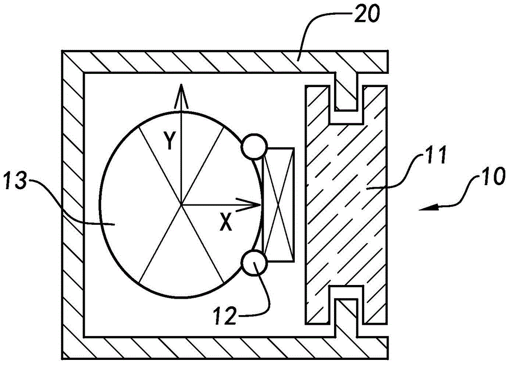
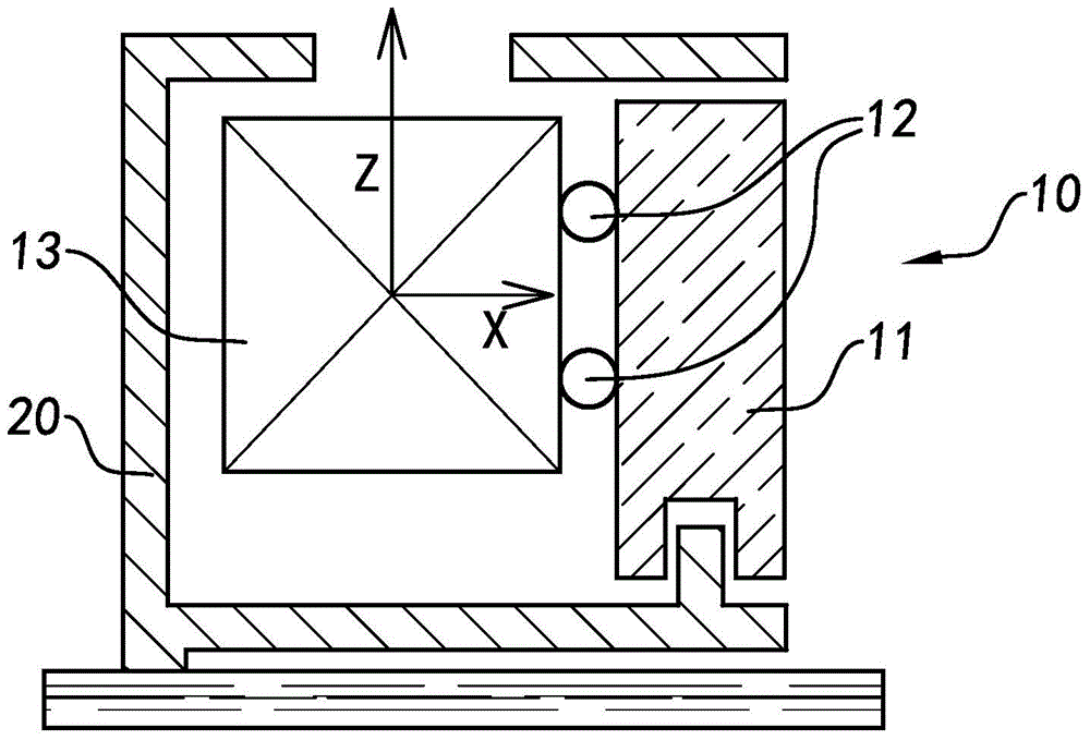
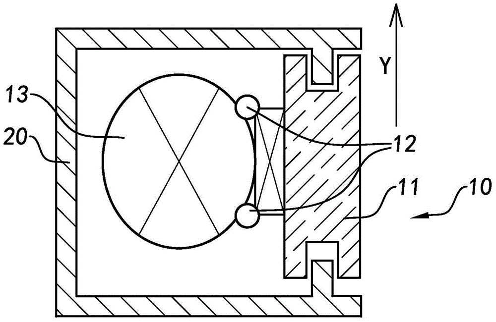
[0035] figure 1 and figure 2 Shown is a schematic structural view of the camera module, the camera module includes a magnetized ball integrated motor, which includes a moving structure 10 and a motor housing 20, the moving structure 10 is movably installed in the motor housing 20 , wherein the moving structure 11 includes a side cover 11 (commonly known as a pot cover), at least one ball 12 (preferably a magnetized ball) and at least one lens 13, and t...


PUM


Abstract

The invention relates to the method for looking for the middle position of a motor, which comprises the steps of firstly acquiring an image taken by a camera module, identifying a mark point in the image through an image detection technology, then calculating the total travel of movement of a side cover through a corresponding algorithm by using software according to variations of the mark point, and thus calculating the middle position of the motor, thereby realizing a function of looking for the middle position of the motor automatically, and improving the calibration efficiency and the success rate.

Description

technical field [0001] The invention relates to the field of mobile phone camera modules, in particular to a method for finding the center position of a magnetized ball integrated motor. Background technique [0002] With the rapid development of photoelectric technology, the application range of camera modules is becoming wider and wider, such as mobile phones, cameras, etc., and people have higher and higher requirements for the clarity of photographed pictures, which makes it particularly important to calibrate camera modules . Keeping the inclination of the optical center of the sensor (Sensor) and the lens (Lens) consistent is very important for the imaging quality of the camera module, and it is also a key factor that determines the quality of the lens module. In the actual production process, it is often corrected by equipment calibration. Ensure that the inclination of the optical center of the sensor and the lens is consistent to improve the imaging quality of the ...

Claims


Application Information

Patent Timeline
IPC IPC(8): H04N17/00
Inventor 陈成权柯海挺徐嘉扬苏海斌傅乾杰周海文
Owner NINGBO SUNNY OPOTECH CO LTD
Why Eureka
Try Eureka