Signal processing device, liquid crystal device, electronic apparatus and signal processing method

a liquid crystal device and signal processing technology, applied in the field of reducing disclination, can solve the problems of discrepancy between whether or not correction is necessary and whether or not correction is actually performed, and the display quality of liquid crystal panels to deteriora

Active Publication Date: 2013-09-19
SEIKO EPSON CORP
View PDF13 Cites 12 Cited by
  • Summary
  • Abstract
  • Description
  • Claims
  • Application Information

AI Technical Summary

Benefits of technology

[0006]An advantage of some aspects of the invention is to provide a technology to resolve the discrepancy between whether or not the correction is necessary and whether or not the correction is actually performed.
[0008]According to the signal processing device, it is possible to resolve the discrepancy between whether or not the correction is necessary and whether or not the correction is actually performed.
[0010]According to the signal processing device, it is possible to narrow the pixels to be corrected.
[0012]According to the liquid crystal device and the electronic apparatus, it is possible to resolve the discrepancy between whether or not the correction is necessary and whether or not the correction is actually performed.
[0014]According to the signal processing method, it is possible to resolve the discrepancy between whether or not the correction is necessary and whether or not the correction is actually performed.

Problems solved by technology

However, in a high definition liquid crystal panel, for example, the distance between the pixels adjacent to each other becomes shorter, an electric field between the pixel electrodes of the two pixels (lateral electric field) is generated, and hence there may be a case where a so-called disclination occurs in which the liquid crystal molecules are aligned in an unintended direction.
The occurrence of the disclination causes a display quality of the liquid crystal panel to deteriorate.
When a correction to suppress a disclination is performed, depending on how to choose a pixel to be corrected, there has been cases of a discrepancy between whether or not the correction is necessary and whether or not the correction is actually performed.

Method used


Image

  • Signal processing device, liquid crystal device, electronic apparatus and signal processing method
  • Signal processing device, liquid crystal device, electronic apparatus and signal processing method
  • Signal processing device, liquid crystal device, electronic apparatus and signal processing method

Examples


first embodiment

1. FIRST EMBODIMENT

1-1. Configuration of Liquid Crystal Device and Problems

[0029]Prior to describing a configuration and an operation of a device in the embodiment, the configuration and problems of the liquid crystal device will be described.

1-1-1. Summary of Liquid Crystal Device

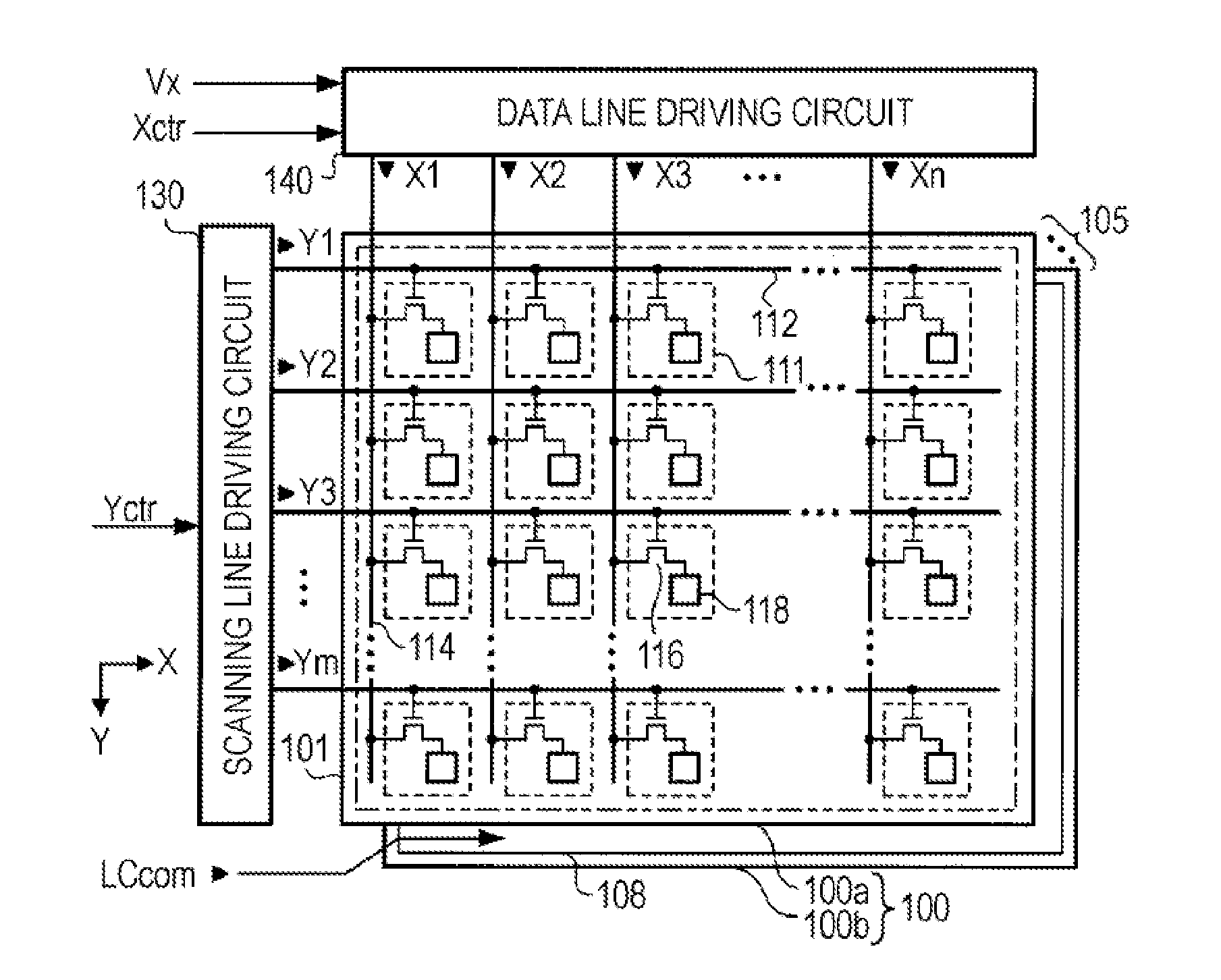
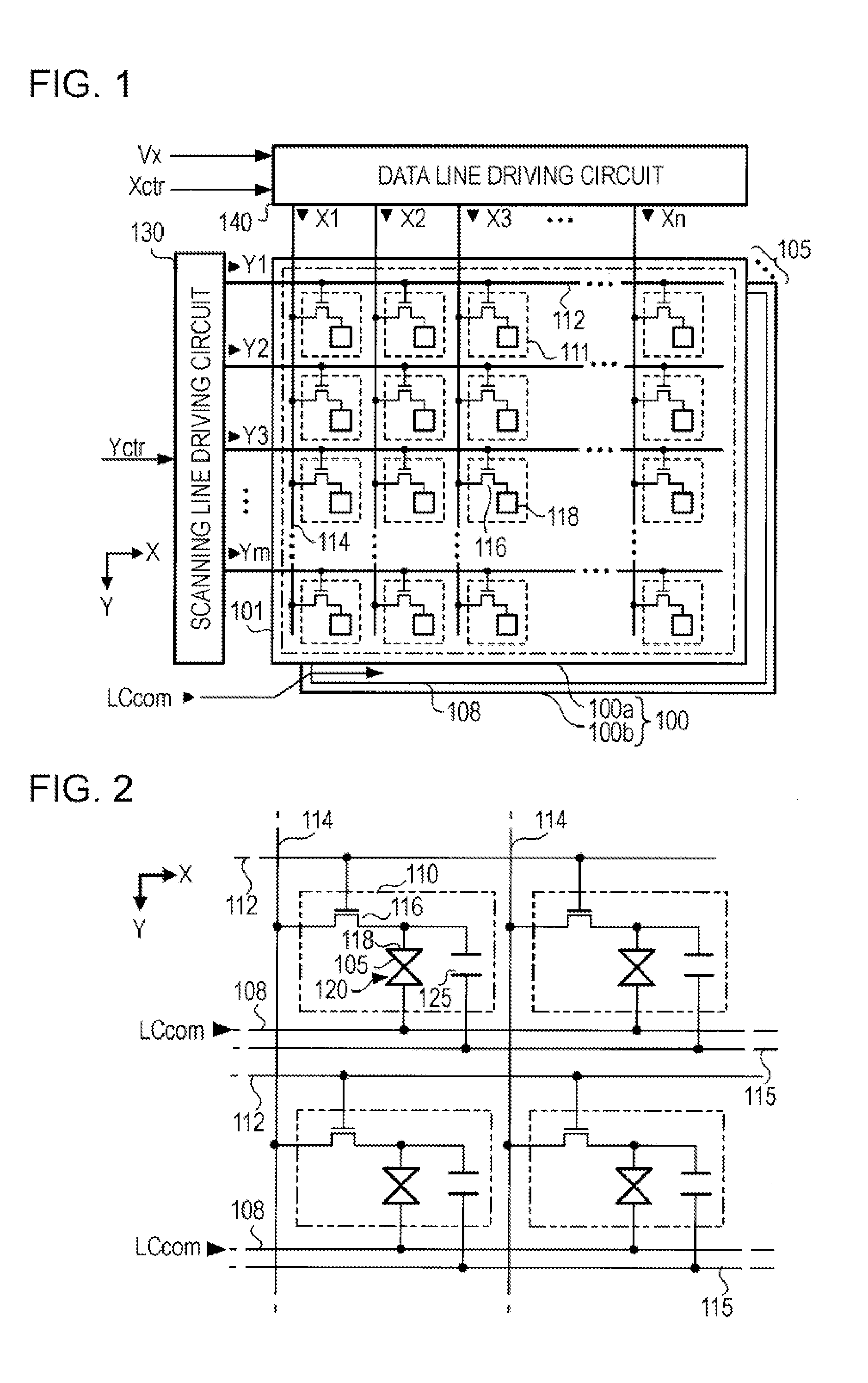
[0030]FIG. 1 is a diagram illustrating a schematic configuration of the liquid crystal device. The liquid display device includes a liquid crystal panel 100, a scanning line drive circuit 130, and a data line drive circuit 140.

[0031]The liquid crystal panel 100 is a device displaying an image according to a supplied signal. The liquid crystal panel 100 includes pixels 111 disposed in a matrix shape with m rows and n columns. The pixels 111 indicates an optical state according to a signal supplied from the scanning line drive circuit 130 and the data line drive circuit 140. The liquid crystal panel 100 displays an image by controlling the optical state of a plurality of pixels 111.

[0032]The liquid crystal p...

second embodiment

2. SECOND EMBODIMENT

[0081]In the first embodiment, for both of the bright pixel and the dark pixel, the correction unit 36 performs the correction by adding the correction amount to the gradation value k of the dark pixel. In the second embodiment, the gradation values are corrected, for the bright pixel, by subtracting the correction amount from the gradation value of the bright pixel W, and for the dark pixel, by adding the correction amount to the gradation value of the dark pixel K respectively. Furthermore, in the second embodiment, the correction of the gradation value is performed for two pixels each on both sides of the risk boundary (four pixels total).

[0082]In the second embodiment, the boundary detection unit 32, as described in the first embodiment, detects a dark pixel adjacent to the risk boundary and a direction of the risk boundary when viewed from the dark pixel. The correction unit 36 performs the correction as described below, with respect to the pixels which sati...

modification example 1

3-1. Modification Example 1

[0089]The conditions for the boundary detection unit 32 to detect the risk boundary is not limited to the conditions (a) to (c) described in the embodiment. In addition to the conditions (a) to (c), the other condition, for example, a condition (d) may be used.

[0090](d) The difference ΔN of the gradation value of the target pixel and that of the adjacent pixel is higher than the threshold value ThN.

(ΔN>ThN)

The pixels on which the corrections are to be performed may be further narrowed by adding this condition. The pixels on which the corrections are to be performed are narrowed to the pixel having a high possibility of the disclination occurring. Therefore, it is possible to suppress the image quality from being decreased due to the excessive changes from the original image displayed by the video signal Vid-in.


PUM


Abstract

A signal processing device using a liquid crystal device having a plurality of pixels includes a storage unit that stores a signal which controls a level of transmittance in a plurality of pixels, a detection unit that, based on the signal that is stored in the storage unit, detects a first pixel associated with a second value which indicates higher transmittance than a first value, and a second pixel adjacent to the first pixel and associated with a fourth value which indicates the higher transmittance than a third value; and a correction unit that corrects the second value so that a difference of the transmittance indicated by the second value and the fourth value decreases. The third value indicates the higher transmittance than the first value, and the fourth value indicates a higher transmittance than the second value.

Description

BACKGROUND[0001]1. Technical Field[0002]The present invention relates to a technology for reducing a disclination.[0003]2. Related Art[0004]Originally, a liquid crystal panel is configured to control an alignment state of liquid crystal molecules using an electric field between a pixel electrode and an opposing electrode in a pixel. However, in a high definition liquid crystal panel, for example, the distance between the pixels adjacent to each other becomes shorter, an electric field between the pixel electrodes of the two pixels (lateral electric field) is generated, and hence there may be a case where a so-called disclination occurs in which the liquid crystal molecules are aligned in an unintended direction. The occurrence of the disclination causes a display quality of the liquid crystal panel to deteriorate. JP-A-2009-25417, JP-A-2009-104053, JP-A-2009-104055, JP-A-2009-237366 and JP-A-2009-237524 disclose technologies for suppressing the occurrence of the disclnation.[0005]Wh...

Claims


Application Information

Patent Timeline
Patent Type & Authority Applications(United States)
IPC IPC(8): G09G3/36
CPCG09G3/3648G09G2320/0209G09G3/36G09G2360/18G09G2340/16G09G2320/0271
Inventor WAKABAYASHI, JUNICHIHOSAKA, HIROYUKIKITAGAWA, TAKUIISAKA, HIDEHITO
Owner SEIKO EPSON CORP
Why Eureka
Try Eureka