Chemical material mixing machine with damping function

A technology for chemical raw materials and mixers, applied in mixers, shaking/oscillating/vibrating mixers, chemical instruments and methods, etc., can solve problems such as mixer damage, large vibration, and increase the frequency of mixer maintenance, and achieve extended use. Longevity, working cost saving, cost reduction effect

Inactive Publication Date: 2017-01-11
WUXI RISHENG CHEM CO LTD
View PDF9 Cites 12 Cited by
  • Summary
  • Abstract
  • Description
  • Claims
  • Application Information

AI Technical Summary

Problems solved by technology

[0005] Aiming at the deficiencies of the prior art, the present invention provides a chemical raw material mixer with a shock-absorbing function, which solves the problem that the traditional mixer will generate large vibrations during the working process, and it is easy to cause the mixer to fail due to excessive vibration. Damage, a problem that increases the frequency of mixer inspections

Method used


Image

  • Chemical material mixing machine with damping function
  • Chemical material mixing machine with damping function
  • Chemical material mixing machine with damping function

Examples


Embodiment 1

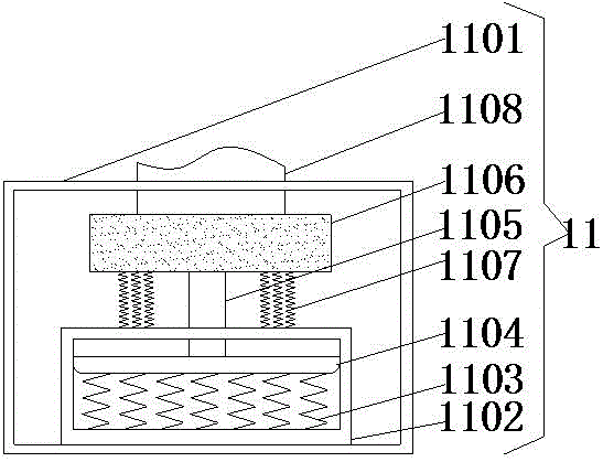
[0022] Example 1: Please refer to figure 2 The damping device 11 includes a first damping housing 1101. The bottom of the inner wall of the first damping housing 1101 is fixedly connected with a fixed box 1102, and the bottom of the inner wall of the fixed box 1102 is fixedly connected with a first damping spring 1103. The top of the vibration spring 1103 is fixedly connected with a piston 1104, and the top of the piston 1104 is fixedly connected with a piston rod 1105. The end of the piston rod 1105 away from the piston 1104 penetrates the fixed box 1102 and extends to the top of the fixed box 1102, and the piston rod 1105 extends to the top of the fixed box 1102. One end of the top of the box 1102 is fixedly connected with a rubber buffer block 1106, the bottom of the rubber buffer block 1106 is fixedly connected to the top of the fixed box 1102 through a second damping spring 1107, and the top of the rubber buffer block 1106 is fixedly connected with a first connecting column...

Embodiment 2

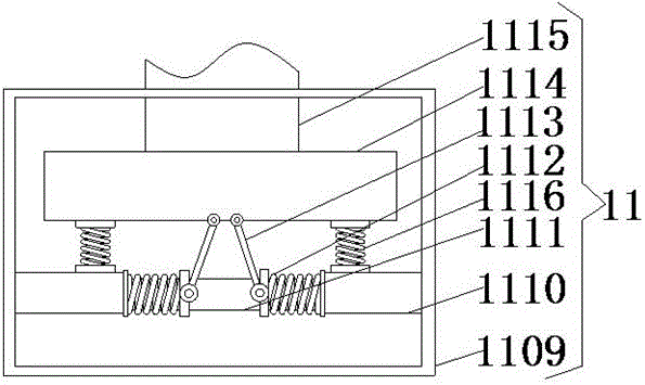
[0023] Example 2: Please refer to image 3 The shock-absorbing device 11 includes a second shock-absorbing shell 1109. Both sides of the inner wall of the second shock-absorbing shell 1109 are fixedly connected with fixing posts 1110, and a fixing rod 1111 is fixedly connected between the two fixing posts 1110, and A third damping spring 1112 is sleeved on both sides of the surface of the rod 1111, one side of the third damping spring 1112 is fixedly connected with the fixed column 1110, and the other side of the third damping spring 1112 is movably connected with a movable rod 1113, A fixed block 1114 is movably connected to the end of the movable rod 1113 away from the third shock-absorbing spring 1112. The top of the fixed column 1110 is fixedly connected to the bottom of the fixed block 1114 through the fourth shock-absorbing spring 1116, and the top of the fixed block 1114 is fixedly connected to the second Connecting column 1115, one end of the second connecting column 111...


PUM


Abstract

The invention discloses a chemical material mixing machine with a damping function. The chemical material mixing machine comprises a bottom plate, wherein two sides of the bottom plate are respectively fixedly connected with a first support pillar and a second support pillar, a barrel is in sliding connection to the top of the bottom plate and is located between the first support pillar and the second support pillar, and one side, close to the barrel, of the first support pillar is fixedly connected with the barrel by an electric expansion link. The chemical material mixing machine with the damping function can effectively solve the problems of conventional mixing machines that severe vibration is generated in operation, the mixing machine is damaged due to excessive vibration, and the mixing machine overhauling frequency is increased, and therefore, the service life of the mixing machine is prolonged, and the working efficiency is improved while the cost is lowered; and the barrel can be moved back and forth during operation, so that the chemical material can be further mixed, and the mixing speed is promoted, and therefore, the working efficiency is improved, and the working cost is saved.

Description

Technical field [0001] The invention relates to the technical field of chemical raw material mixers, in particular to a chemical raw material mixer with shock absorption function. Background technique [0002] The mixer is a mechanical equipment that uses mechanical force and gravity to uniformly mix two or more materials. During the mixing process, the contact surface area of ​​the materials can be increased to promote chemical reactions; it can also accelerate physical changes. The mixer is divided into four categories: gas and low viscosity liquid mixer, medium and high viscosity liquid and paste mixing machine, thermoplastic material mixer, powder and granular solid material mixing machine, gas and low viscosity liquid mixer is characterized by structure Simple, no rotating parts, small maintenance and repair, and low energy consumption. This type of mixing machinery is divided into four types: air mixing, pipeline mixing, jet mixing and forced circulation mixing. The mixer ...

Claims


Application Information

Patent Timeline
Patent Type & Authority Applications(China)
IPC IPC(8): B01F11/00
CPCB01F31/56B01F31/70
Inventor 杜旭升
Owner WUXI RISHENG CHEM CO LTD
Why Eureka
Try Eureka