Unlock instant, AI-driven research and patent intelligence for your innovation.

Shaft sleeve part loading mechanism

A technology for shaft sleeves and parts, which is applied in the field of shaft sleeve parts feeding mechanism, can solve the problems of high labor intensity, low work efficiency, and affecting production tempo, etc., to reduce labor intensity, reduce labor costs, and improve production tempo Effect

Inactive Publication Date: 2017-01-11
ANHUI JEE AUTOMATION EQUIP CO LTD
View PDF6 Cites 10 Cited by
  • Summary
  • Abstract
  • Description
  • Claims
  • Application Information

AI Technical Summary

Problems solved by technology

[0002] The shaft sleeve part is a round tubular part. The shaft sleeve is pressed onto the shaft by a press and used as the inner ring of the needle roller bearing. In the current technology, the shaft sleeve is pressed manually. to the shaft, and then press-fit, this manual method is not only labor-intensive, but also greatly affects the production cycle due to low work efficiency

Method used


Image

  • Shaft sleeve part loading mechanism
  • Shaft sleeve part loading mechanism
  • Shaft sleeve part loading mechanism

Examples


Embodiment Construction

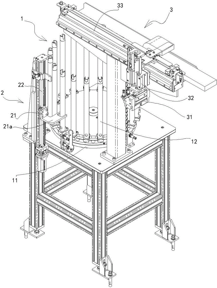
[0017] see figure 1 , In the present embodiment, the loading mechanism for shaft sleeve parts includes a storage turntable 1 , a lifting device 2 and a grabbing mechanism 3 .

[0018] like figure 1 and figure 2 As shown, the storage carousel 1 has a rotatable chassis 11, on the chassis 11, vertical material columns 12 are evenly arranged along the outer circumference of the chassis 11, and the shaft sleeves 10 are set on the material columns 12 in series. The motor 13 drives the chassis 11 to rotate according to the angle index.

[0019] like figure 1 and image 3 As shown, the lifting device 2 is located on the periphery of the turntable 1, and is a screw rod slider mechanism. The screw rod 22 is installed vertically, the slider 21 can move up and down along the screw rod, and a horizontal dial is fixedly arranged on the slider 21. The fork 21a, the shift fork 21a is used to lift the sleeve 10 set on the material column 12, the second servo motor 23 drives the screw rod...


PUM


Abstract

The invention discloses a shaft sleeve part loading mechanism. The shaft sleeve part loading mechanism is characterized by comprising a material storage rotary table, a lifting device and a material grabbing mechanism, wherein the material storage rotary table is provided with a rotatable chassis, vertical material columns are uniformly arranged along the outer periphery of the chassis, shaft sleeves sleeve the material columns in strings, and the chassis is driven by a servo motor to rotate in an indexing manner according to angles; the lifting device which is located in the outer periphery of the turntable is a lead screw slide block mechanism, a lead screw is driven by the servo motor to rotate, a shifting fork is driven by the lead screw to move up and down, and the shifting fork lifts the height of the shaft sleeves sleeving the material columns; the lifting device and the material grabbing mechanism are arranged in lifting and grabbing positions in a matched manner, top end shaft sleeves on the material columns which are lifted by the shifting fork are grabbed by virtue of a clamping claw in the grabbing mechanism, and are driven by a rodless air cylinder to be placed in locating tools. By arranging a control circuit in a matched manner, the shaft sleeve parts can be automatically loaded to replace manual work, so that the degree of automation of equipment can be greatly improved.

Description

technical field [0001] The invention relates to a feeding mechanism for shaft sleeve parts, more specifically to a feeding mechanism for grabbing shaft sleeves from a material bin to a pressing position during the press-fitting process of shaft sleeve parts. Background technique [0002] The shaft sleeve part is a round tubular part. The shaft sleeve is pressed onto the shaft by a press and used as the inner ring of the needle roller bearing. In the current technology, the shaft sleeve is pressed manually. To the shaft, and then press-fit, this manual method not only has a high labor intensity for workers, but also greatly affects the production cycle due to low work efficiency. Contents of the invention [0003] In order to avoid the shortcomings of the above-mentioned prior art, the present invention provides a shaft sleeve parts feeding mechanism. The shaft sleeve can be automatically loaded and pressed by using the feeding mechanism of the present invention, and the sh...

Claims


Application Information

Patent Timeline
IPC IPC(8): B23P19/027B23P19/00
CPCB23P19/006B23P19/027
Inventor 刘蕾宋增广陆煜徐明涛
Owner ANHUI JEE AUTOMATION EQUIP CO LTD
Features
  • R&D
  • Intellectual Property
  • Life Sciences
  • Materials
  • Tech Scout
  • Unparalleled Data Quality
  • Higher Quality Content
  • 60% Fewer Hallucinations
Learn More