Method for locking screw automatically

A technology for automatic locking of screws and screws, applied in metal processing, metal processing equipment, manufacturing tools, etc., can solve the problems of cumbersome operation and low work efficiency, and achieve the effect of strong flexibility, improved yield, and improved work efficiency.

Inactive Publication Date: 2017-01-11
ZHONGSHAN HEYING INTELLIGENT EQUIP CO LTD
View PDF8 Cites 15 Cited by
  • Summary
  • Abstract
  • Description
  • Claims
  • Application Information

AI Technical Summary

Problems solved by technology

The above two methods all have problems such as

Method used


Image

  • Method for locking screw automatically
  • Method for locking screw automatically
  • Method for locking screw automatically

Examples


Embodiment Construction

[0034] In order to make the technical problems, technical solutions and beneficial effects solved by the present invention clearer, the present invention will be further described in detail below in conjunction with the accompanying drawings and embodiments. It should be understood that the specific embodiments described here are only used to explain the present invention, not to limit the present invention.

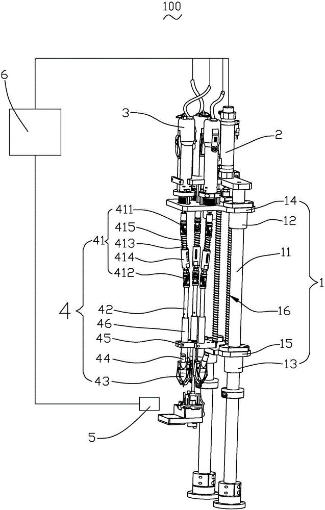
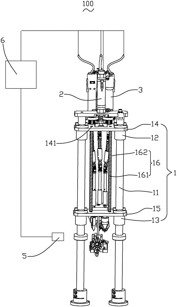
[0035] Please also see figure 1 and figure 2 ,in figure 1 The structural representation of the automatic locking screw machine provided by the present invention, figure 2 for figure 1 A structural schematic diagram of another angle of the automatic locking screw machine shown. The automatic locking screw machine 100 includes a support frame 1, a cylinder 2, an electric screwdriver 3, a screw clamping device 4, a CCD visual detector 5, a control device 6 and a screw feeding device (not shown).

[0036] The support frame 1 is a double guide rod and guide sleeve supp...


PUM


Abstract

The invention discloses a method for locking a screw automatically. The method for locking the screw automatically comprises the following steps that a to-be-assemble product is assembled to an installation position, and a CCD visual detector scans the shape of the to-be-assemble product and uploads scanned data to a control device; the control device calculates the coordinates of a screw hole of the to-be-assemble product according to the received shape data of the to-be-assemble product; the control device controls a electric screwdriver to act and drives a screw clamping device to move, and thus the screw clamping device is located over the screw hole in the corresponding position; the screw clamping device clamps the screw supplied by a screw feed device; and the control device controls an air cylinder to push the electric screwdriver and the screw clamping device to move downwards, thus the screw is inserted into the screw hole in the corresponding position, the electric screwdriver is started, the screw is screwed into the screw hole, and product assembly is completed. The provided method for locking the screw automatically is high in work efficiency and high in product assembly yield.

Description

technical field [0001] The invention relates to the technical field of screw locking equipment, in particular to a method for automatically locking screws. Background technique [0002] Most structural products are formed by assembling several parts. In the process of product assembly, the connection method of each part is mainly realized by screw connection. Therefore, one or more screws need to be driven in during the assembly process of different products. [0003] In the related art, the screw tapping of the product is mainly carried out by manual manual tapping or a single-axis screw machine. When manually tapping screws, the operator holds an electric screwdriver and manually puts the screws into the corresponding screw holes of the product to perform locking work; while using a single-axis screw machine, only one screw can be tapped at a time, and After tapping a screw, it is necessary to shift the single-axis screwdriver so that it corresponds to the next screw hol...

Claims


Application Information

Patent Timeline
IPC IPC(8): B23P19/06
CPCB23P19/06
Inventor 张帆
Owner ZHONGSHAN HEYING INTELLIGENT EQUIP CO LTD
Why Eureka
Try Eureka