Shear type gripper

A gripper and scissor unit technology, which is applied in the field of scissor mechanism, can solve the problems that the working platform of the elevator is not stable, easy to bend, and the processing accuracy is not high, so as to achieve convenient and fast clamping process and stable clamping Effect

Inactive Publication Date: 2017-01-11
FOSHAN HECAI TECH SERVICE +1
View PDF4 Cites 3 Cited by
  • Summary
  • Abstract
  • Description
  • Claims
  • Application Information

AI Technical Summary

Problems solved by technology

The main disadvantage of most scissor mechanisms is that under the action of multi-directional force, the strength and rigidity of the structure in the direction of the force are not enough to bear the load-bearing effect of the force, it is prone to distortion, and the safety is not high
In addition, the load capacity of the current scissor mechanism is not high, and these weaknesses limit its wider application
If a double parallel scissor mechanism is used, although the load capacity can be enhanced, there will be a problem of asynchronous work between the two scissor mechanisms, resulting in problems such as unstable operation of the working platform of the elevator
[0004] At present, when processing some objects that need to change the diameter, it is often necessary to standardize its inner diameter or outer diameter. However, the equipment currently used has not been able to maintain the same center and can be arbitrarily stretched on the same diameter. The processing accuracy is not high. Low production efficiency

Method used


Image

  • Shear type gripper
  • Shear type gripper
  • Shear type gripper

Examples


Embodiment Construction

[0022] The technical solutions of the present invention will be further described below in conjunction with the accompanying drawings and through specific implementation methods.

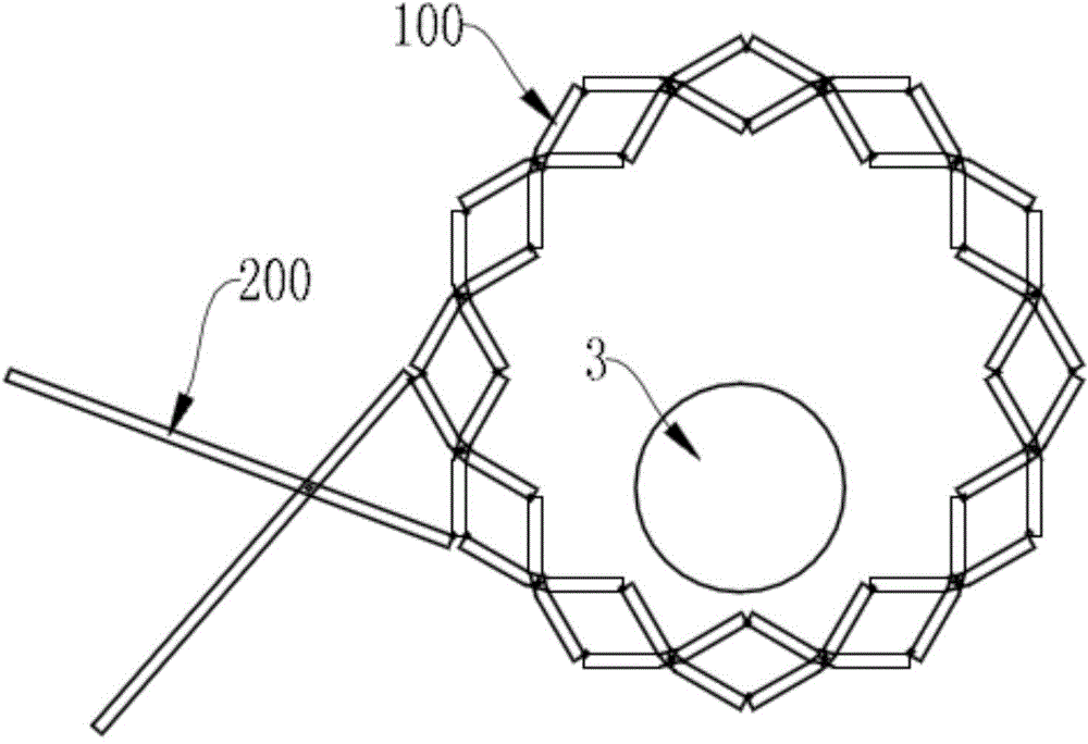
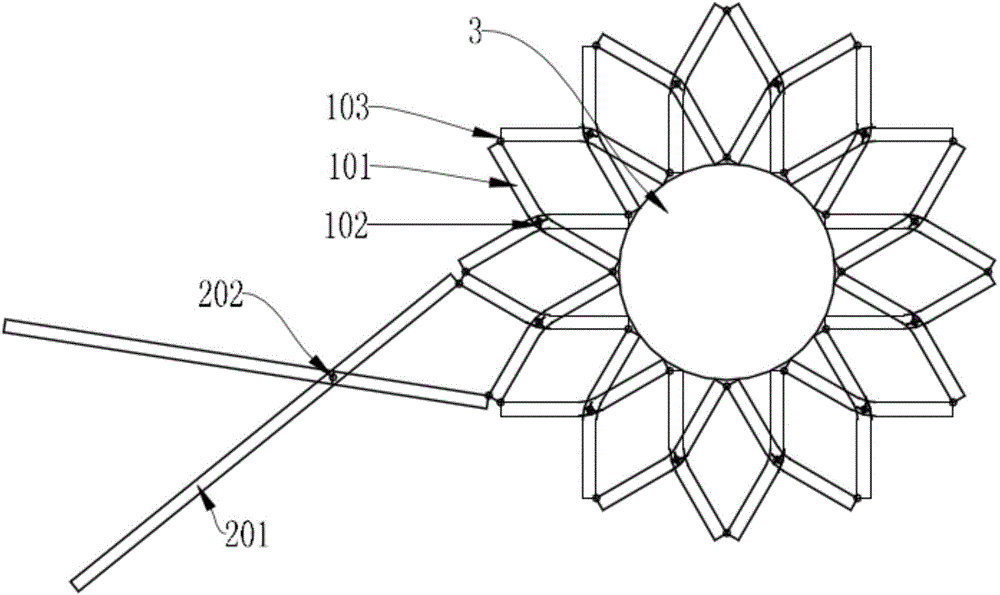
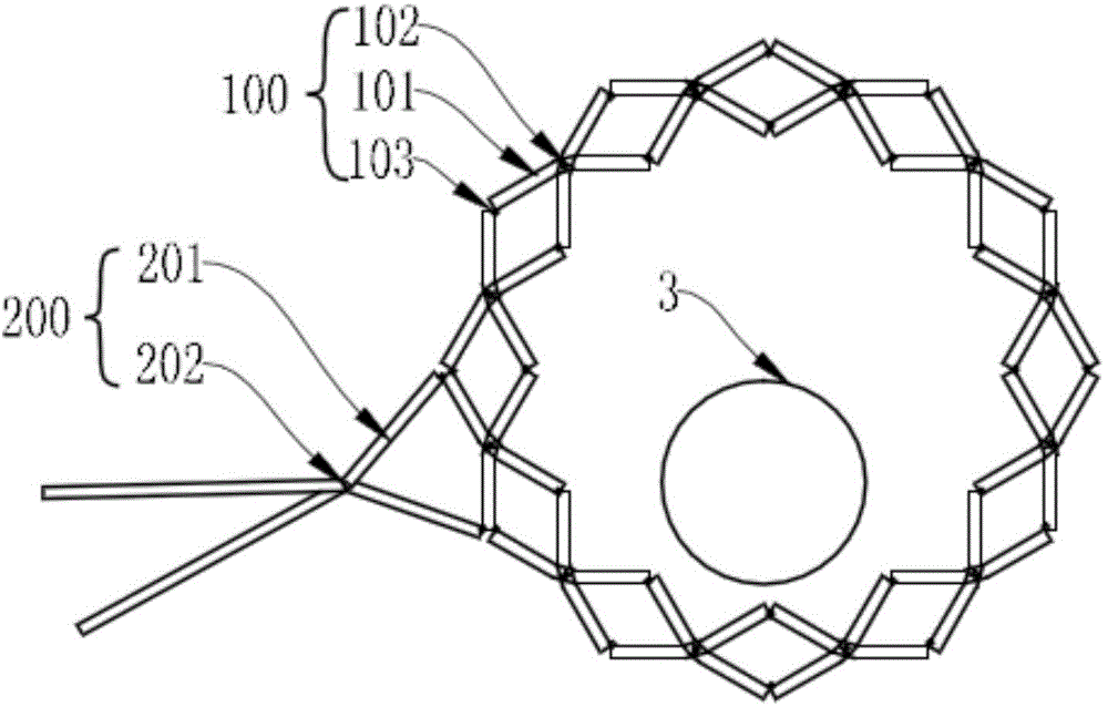
[0023] Such as figure 1 and figure 2 As shown, a scissor gripper; includes a synchronously telescopic clamping ring 100 and a drive assembly 200, and the drive assembly 200 drives the clamping ring 100 to realize synchronous telescopic expansion;

[0024] The clamping ring 100 is a ring structure formed by connecting several scissor units end to end through connecting shafts 103. The scissor units are an X-shaped structure composed of connecting rods 101 and scissor shafts 102. The middle part of the connecting rod 101 is hinged by the scissor shaft 102; the two ends of the connecting rod 101 are hinged with the connecting rod 101 at the corresponding position in the adjacent scissor unit through the connecting shaft 103;

[0025] The drive assembly 200 is an X-shaped structure composed of a driv...


PUM


Abstract

The invention discloses a shear type gripper which comprises a clamping ring capable of achieving synchronous stretching and contracting and a drive assembly. The drive assembly drives the clamping ring to achieve synchronous stretching and contracting. The clamping ring is of a ring-shaped structure formed by connecting multiple shear type units end to end through connecting rotating shafts end to end. Each shear type unit is of an X-shaped structure composed of connecting rods and a shear type rotating shaft, wherein the middle portions of the two connecting rods are hinged to each other through the shear type rotating shaft, and the two ends of the connecting rods are hinged to the connecting rods at the corresponding positions in the adjacent shear type units through the corresponding connecting rotating shafts. The drive assembly is of an X-shaped structure composed of drive rods and a drive rotating shaft, wherein the two drive rods rotate around the drive rotating shaft, and one ends of the two drive rods are hinged to the two connecting rods of the same shear type unit.

Description

technical field [0001] The invention relates to the field of scissor mechanism, in particular to a scissor gripper. Background technique [0002] The scissor mechanism has a wide range of applications and developments, such as foldable tents, retractable door curtains, elevators, foldable desk lamps or robotic arms, etc. It is characterized by a large expansion ratio, can be extended for a long distance and a large span, and when it shrinks, it occupies a small space, so it is used in many industries. [0003] What adopt in the application of most scissor mechanism at present is single-sided scissor mechanism or double parallel scissor mechanism, what adopt as door curtain is single-sided scissor mechanism, what elevator adopts is double parallel scissor mechanism. The main disadvantage of most scissor mechanisms is that under the action of multi-directional force, the strength and rigidity of the structure in the direction of the force are not enough to bear the load-beari...

Claims


Application Information

Patent Timeline
Patent Type & Authority Applications(China)
IPC IPC(8): B23Q3/00
CPCB23Q3/00B23Q2703/10
Inventor 不公告发明人
Owner FOSHAN HECAI TECH SERVICE
Why Eureka
Try Eureka