
An automatic conveying mechanism for machining equipment

An automatic conveying and machining technology, which is applied in metal processing and other directions, can solve the problems affecting material conveying and processing, the conveying position is not easy to control, and cannot meet the requirements of rapid production, etc., to achieve the effect of improving production efficiency, rich functions, and simple structure

Inactive Publication Date: 2018-09-07
禹州市鼎锋机械科技有限公司
View PDF6 Cites 0 Cited by
  • Summary
  • Abstract
  • Description
  • Claims
  • Application Information

AI Technical Summary

Problems solved by technology

[0002] With the continuous development of industrial technology and science and technology, China's machining equipment has also developed rapidly. In the process of machining, the conveying mechanism is an indispensable part of machining equipment. It is mainly used to carry materials and transfer workpieces. With the continuous development of modern industry, the automatic conveying mechanism has replaced the manual conveying, realizing the automatic operation of the production process, thus improving the working conditions and reducing the labor intensity. It is an important means to improve production efficiency. The traditional manual feeding method, Waste of manpower and time, low work efficiency, cannot meet the needs of rapid production, especially when handling tubular materials, the labor intensity is high, because the tubular materials are not easy to fix, the conveying position is not easy to control during the transportation process, and it is easy to appear The phenomenon of material rolling affects the conveying and processing of materials and reduces production efficiency. Therefore, it is necessary to design a machine with reasonable design, simple structure, low production cost, low labor intensity, time-saving and labor-saving, high degree of automation, accurate conveying position and high work efficiency. , stable work, safe and reliable, long service life, strong practical performance, improved production efficiency, and a wide range of applicable machining equipment automatic conveying mechanism is very necessary, which is of great help to improve machining efficiency and reduce labor intensity function and meaning

Method used


Image

  • An automatic conveying mechanism for machining equipment
  • An automatic conveying mechanism for machining equipment

Examples


Embodiment 1

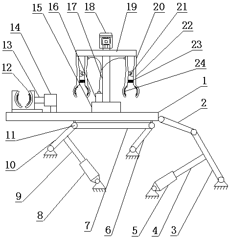
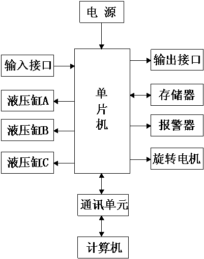
[0016] Such as figure 1 and figure 2 Shown, a kind of automatic conveying mechanism of machining equipment, it comprises transmission plate 1 and single-chip microcomputer, described transmission plate 1 is connected with connecting rod A2, and described connecting rod A2 is connected with fork A3, and described fork A3 is connected with a piston rod A4 and a hydraulic cylinder A5, and the bottom of the transmission plate 1 is equipped with a roller 11, and the roller 11 is connected with a connecting rod B7, and the connecting rod B7 is connected with a swing rod B6 and a swing rod C10 , the swing rod C10 is connected with a piston rod B9 and a hydraulic cylinder B8, the upper part of the transmission plate 1 is equipped with a clamping device 12 and a support seat 15, and the clamping device 12 is connected with a piston rod 13C and hydraulic pressure Cylinder C14, the upper end of the support seat 15 is equipped with a cylinder 16 and a support frame 17, the top of the su...

Embodiment 2

[0019] Such as figure 1 and figure 2 Shown, a kind of automatic conveying mechanism of machining equipment, it comprises transmission plate 1 and single-chip microcomputer, described transmission plate 1 is connected with connecting rod A2, and described connecting rod A2 is connected with fork A3, and described fork A3 is connected with a piston rod A4 and a hydraulic cylinder A5, and the bottom of the transmission plate 1 is equipped with a roller 11, and the roller 11 is connected with a connecting rod B7, and the connecting rod B7 is connected with a swing rod B6 and a swing rod C10 , the swing rod C10 is connected with a piston rod B9 and a hydraulic cylinder B8, the upper part of the transmission plate 1 is equipped with a clamping device 12 and a support seat 15, and the clamping device 12 is connected with a piston rod 13C and hydraulic pressure Cylinder C14, the upper end of the support seat 15 is equipped with a cylinder 16 and a support frame 17, the top of the su...


PUM


Abstract

The invention relates to an automatic conveying mechanism for a machining device. The automatic conveying mechanism comprises a conveying plate and a single-chip microcomputer. The conveying plate is connected with a connecting rod A connected with a swinging rod A. The swinging rod A is connected with a piston rod A and a hydraulic cylinder A. Wheels are arranged at the bottom of the conveying plate and connected with a connecting rod B. The connecting rod B is connected with a swinging rod B and a swinging rod C. The swinging rod C is connected with a piston rod B and a hydraulic cylinder B. A clamping device and a supporting base are arranged at the upper portion of the conveying plate. The clamping device is connected with a piston rod C and a hydraulic cylinder C. An air cylinder and a supporting frame are arranged at the upper end of the supporting base. A rotation motor is arranged on the top of the supporting frame and connected with a rotation beam. The rotation beam is provided with mechanical claws. The single-chip microcomputer is connected with a communication unit connected with a computer. The automatic conveying mechanism has the beneficial effects that design is reasonable, the structure is simple, time and labor are saved, and the automation degree is high; and the conveying position is accurate, the work efficiency is high, work is stable, the service life is long, practical performance is high, and the production efficiency is improved.

Description

technical field [0001] The invention belongs to the technical field of machining equipment, and in particular relates to a conveying mechanism, in particular to an automatic conveying mechanism of machining equipment. Background technique [0002] With the continuous development of industrial technology and science and technology, China's machining equipment has also developed rapidly. In the process of machining, the conveying mechanism is an indispensable part of machining equipment. It is mainly used to carry materials and transfer workpieces. With the continuous development of modern industry, the automatic conveying mechanism has replaced the manual conveying, realizing the automatic operation of the production process, thus improving the working conditions and reducing the labor intensity. It is an important means to improve production efficiency. The traditional manual feeding method, Waste of manpower and time, low work efficiency, cannot meet the needs of rapid prod...

Claims


Application Information

Patent Timeline
Patent Type & Authority Patents(China)
IPC IPC(8): B23Q7/04B23Q7/00
CPCB23Q7/00B23Q7/048
Inventor 张振堂
Owner 禹州市鼎锋机械科技有限公司
Learn More