
Viscosity detection method for ink-jet printer

A detection method and inkjet printer technology are applied in the directions of measuring device, printing, flow characteristics, etc., which can solve the problems of complex structure, many nozzle components, high production and maintenance costs, and achieve the effect of ensuring printing quality.

Active Publication Date: 2017-01-11
XIAMEN YINGJIEHUA ELECTROMECHANICAL TECH
View PDF9 Cites 4 Cited by
  • Summary
  • Abstract
  • Description
  • Claims
  • Application Information

AI Technical Summary

Problems solved by technology

Specifically, a specific viscometer is used in the inkjet printer to perform intermittent viscosity detection, and the charging time of ink dots is adjusted according to the viscosity detection results. This method has weak real-time performance, and at the same time, because the structure of the viscosity detector is complex, it is not easy to manufacture. , easy to block when used, resulting in inaccurate detection of viscosity, and high production and maintenance costs
[0007] There is also a method of detecting viscosity by detecting and calculating ink speed, which uses two phase detectors, detects pulse signals with ink dots on the two phase detectors, calculates the time difference of the pulse signals, and two The speed can be calculated by the distance between the phase detectors. In this method, the ink line running speed is set in advance when the ink viscosity is good, and the change of the ink viscosity is judged by detecting the change of the ink line speed. Currently Setting two phase detectors in the nozzle results in many nozzle components and complex structure, such as figure 1 As mentioned above, two phase detectors are generally arranged on both sides of the high-voltage deflection plate

Method used


Image

  • Viscosity detection method for ink-jet printer
  • Viscosity detection method for ink-jet printer
  • Viscosity detection method for ink-jet printer

Examples


Embodiment Construction

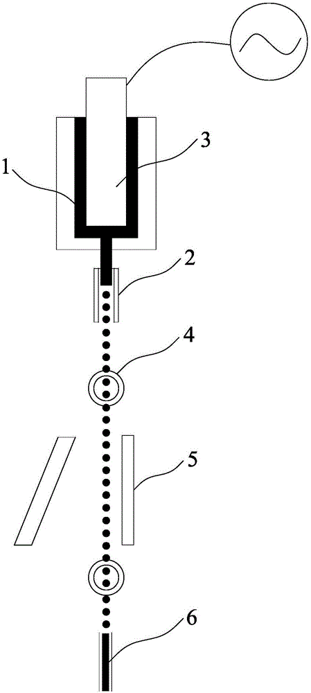
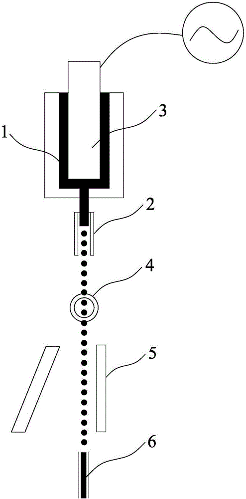
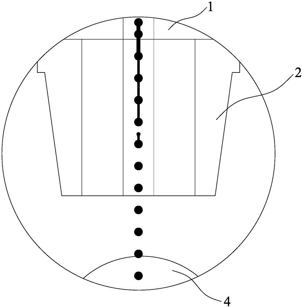
[0024] The inkjet printer viscosity detection method disclosed by the present invention, its steps are:

[0025] 1. Set an initial crystal oscillator frequency f, obtain the period T of ink dot formation according to the crystal oscillator frequency, divide the period T into N equal parts, and use is a time gradient;

[0026] 2. Within a period T, starting from the time starting point of a period, each increment The charging pole will charge several ink dots at a certain time, and record the time value t of each charging n1 , 1≤n≤N;

[0027] Third, at each time gradient Inside, the phase detector continuously detects a dot with a dot, if a dot with a dot is detected, a pulse signal is generated and sent to the main controller, and the time gradient is recorded The time value t when a pulse signal is detected within n2 , if at this time gradient If the internal main controller does not detect the pulse signal, the charging pulse time will be delayed time;

[0028]...


PUM


Abstract

The invention discloses a viscosity detection method for an ink-jet printer. The viscosity detection method comprises the following steps: setting an initial crystal oscillator frequency f, acquiring an ink dot forming cycle T according to the crystal oscillator frequency, equally dividing the cycle T into N parts, and taking T / N as a time gradient; within the cycle T, starting from the time start point of the cycle, enabling a charging electrode to charge a plurality of ink dots in every time increment of T / N, and recording the time value tn1 of each time of charging, wherein n is more than or equal to 1 and less than or equal to N; within each time gradient T / N, enabling a phase detector to continually detect charged ink dots and to send detected pulse signals to a main controller, and recording the time value tn2 at which the pulse signals are detected; and calculating the time difference (delta T=tn2-tn1) between tn1 and tn2, finally, calculating the ink line running speed V (V=S / delta T) according to the time difference and fixed distance S between a charging bath and the phase detector, and judging changes of the ink viscosity according to the running speed V. The viscosity detection method realizes ink viscosity detection through a detection electrode to achieve the purpose of adaptively adjusting the charging time.

Description

technical field [0001] The invention relates to the technical field of industrial inkjet printers, in particular to a method for detecting the viscosity of an inkjet printer. Background technique [0002] The inkjet printer is a device that is controlled by software and uses a non-contact method to mark on the product. It is mainly composed of an inkjet coding system and an ink circuit system. Among them, the electric field deflection continuous inkjet printer uses charged ink dots The deflection in the electric field is used to realize the reduction of characters, which is usually referred to as CIJ inkjet printer for short. [0003] like figure 1 and 2 As shown, the working principle of the CIJ inkjet printer is that a solvent-based quick-drying ink (ink) is ejected from the nozzle under the pressure of the pressure pump. When the ink passes through the nozzle 1, it is broken into a series of continuous ink by the action of the oscillator 2 Ink droplets with equal spaci...

Claims


Application Information

Patent Timeline
Patent Type & Authority Applications(China)
IPC IPC(8): B41J2/07G01N11/00
CPCB41J2/07G01N11/00
Inventor 魏万贤何建荣
Owner XIAMEN YINGJIEHUA ELECTROMECHANICAL TECH
Features
  • Generate Ideas
  • Intellectual Property
  • Life Sciences
  • Materials
  • Tech Scout
  • Unparalleled Data Quality
  • Higher Quality Content
  • 60% Fewer Hallucinations
Learn More