Channel culvert formwork car

A formwork car and channel technology, applied in construction, artificial island, infrastructure engineering, etc., can solve the problems of long construction time, hidden safety hazards, high mechanical and labor costs, and achieve convenient movement, save construction costs, and speed up construction progress. Effect

Active Publication Date: 2017-01-11
NANTONG JIANGHUA MASCH CO LTD
View PDF5 Cites 2 Cited by
  • Summary
  • Abstract
  • Description
  • Claims
  • Application Information

AI Technical Summary

Problems solved by technology

[0003] The invention provides a channel culvert formwork vehicle which is convenient for moving and used for channel culvert construction, which solves the problems of long construction time for erecting steel pipe supports, installing formwork and pouring concrete, high mechanical and labor costs, and potential safety hazards

Method used


Image

  • Channel culvert formwork car
  • Channel culvert formwork car
  • Channel culvert formwork car

Examples


Embodiment 1

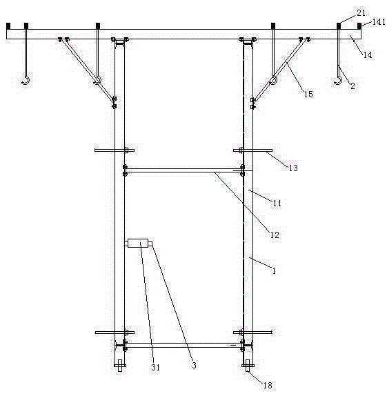
[0034] Embodiment one, see figure 1 , a channel culvert formwork vehicle, characterized in that it includes a vehicle frame 1. The frame 1 includes a pole 11 . The lower end of each vertical rod 11 is provided with road wheels 18 . Horizontally adjacent uprights are connected together by a number of transverse connecting rods 12 distributed along the up-down direction. The transverse connecting rod 12 and the upright rod 11 are detachably connected together by bolts fitting the connecting plate. Adjusting bolts 13 are provided on both sides of the vehicle frame 1 in the width direction (the left and right directions in the figure, the width direction of the channel culvert during use). Adjusting bolts 13 protrude from the vehicle frame 1 along the width direction of the vehicle frame. The adjusting bolt 13 is arranged on the pole 11 . The adjusting bolts 13 are at least distributed into two rows along the up-down direction, and distributed into two rows along the front-re...

Embodiment 2

[0042] Embodiment two, the difference with embodiment one is:

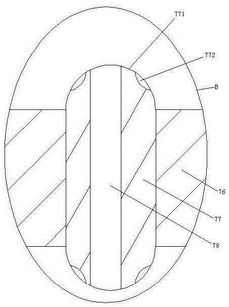
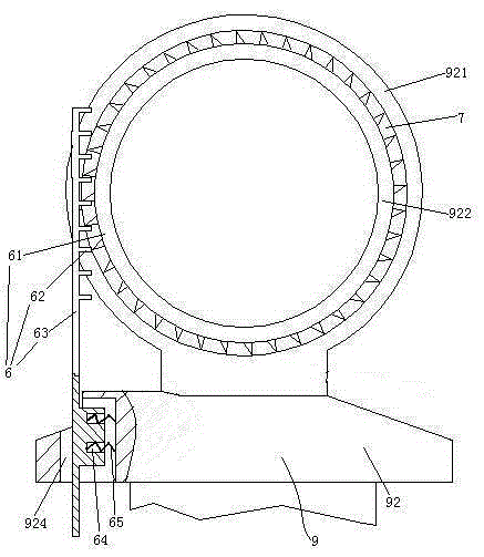
[0043] see Figure 6 , The vehicle frame 1 is provided with a static support foot 17 and a walking wheel installation rod 9 . Static support feet 17 and vehicle frame 1 are screwed together to realize liftable connection. The static support feet 17 can be adjusted to be lower than the walking wheels 18 . The road wheel mounting rod 9 includes a lower section 91 and an upper section 92 . The road wheels 18 are connected to the lower end of the lower section 91 . The upper end of the lower section 91 is slidably sleeved on the lower end of the upper section 92 . The lower section 91 is provided with a damping spring 93 supporting the upper section 92 . The upper end of the upper section 92 is provided with a connecting ring 921 . An inner ring 922 passes through the connecting ring 921 . The inner ring 922 is connected with the connecting ring 921 through the rubber ring 7 . The inner ring 922 is pierced wit...

Embodiment 3

[0050] Embodiment three, the difference with embodiment two is:

[0051] see Figure 11 , The road wheel mounting rod 9 is also provided with a drive mechanism 6. The inner ring 922 is rotatably connected to the rubber ring 7 , and the rubber ring 7 is fixedly connected with the connecting ring 921 .

[0052] The drive mechanism 6 includes a ratchet 61 , a pawl 62 for driving the ratchet, and a drive lever 63 . The ratchet 61 is coaxially connected with the inner ring 922 . The ratchet 61 is integrated with the inner ring 922 . The pawl 62 is fixedly connected to one end of the driving rod 63 . The upper section 92 is provided with a sliding hole 924 . The other end of the driving rod 63 can slide through the sliding hole 924 two-dimensionally. The lower end of the drive rod 63 is slidably hooked to the lower section 91 along the radial direction of the connecting ring 921 (see Figure 6 ) are fixed together. The driving rod 63 is provided with a storage hole 64 . The...


PUM


Abstract

The invention relates to building construction machinery and discloses a channel culvert formwork car. The channel culvert formwork car comprises a car frame. The car frame is provided with travelling wheels and a handle rod. Two main beams which are arranged longitudinally and extend transversely are arranged at the upper end of the car frame. The two ends of each main beam extend out of the car frame transversely and are each provided with two rows of hooks distributed transversely. The two sides in the width direction of the car frame are provided with adjusting bolts. A motor is provided with the handle rod. The handle rod is provided with a sleeve pipe. An elastic adjusting mechanism is arranged between the handle rod and the sleeve pipe. The elastic adjusting mechanism comprises a base pipe, a clamping layer and a pretightening force adjusting structure. The clamping layer is composed of a plurality of friction strips. The friction strips are provided with a plurality of sliding rods arranged on the base pipe in a penetrating mode. Third springs used for driving the sliding rods to move outwards so as to drive the friction strips to abut against the sleeve pipe are arranged at the inner ends of the sliding rods. The channel culvert formwork car has the advantages of being convenient to move and capable of being used for channel culvert construction, and the problems that the construction time for erecting steel pipe support mounting formworks and pouring concrete is long, and the mechanical and labor cost are high are solved.

Description

technical field [0001] The invention relates to machinery for building construction, in particular to a channel culvert formwork vehicle. Background technique [0002] In the process of expressway channel culvert construction, the traditional construction method is to install and bind segmental steel bars after the channel foundation construction is completed, use a crane to install the formwork, and erect steel pipe brackets in the channel for formwork support and reinforcement construction. Build and disassemble the construction in a cycle in turn until the construction of the entire channel culvert is completed. The construction time of this method is longer, the cost of machinery and labor is higher, and there are more potential safety hazards. Contents of the invention [0003] The invention provides a channel culvert formwork vehicle which is convenient to move and is used for channel culvert construction, which solves the problems of long construction time for erec...

Claims


Application Information

Patent Timeline
Patent Type & Authority Applications(China)
IPC IPC(8): E02D29/045
Inventor 危金兰
Owner NANTONG JIANGHUA MASCH CO LTD
Why Eureka
Try Eureka