A drilling and anchoring structure for monitoring cracks in the surrounding rock of the floor and its construction method

A construction method and drilling anchor technology, which are used in earth-moving drilling, wellbore/well components, construction, etc., can solve problems such as increased monitoring costs, hidden safety hazards in normal construction, and shallow bottom plate drilling holes, etc., and achieve savings. Instrument loss and materials, avoid collapse hole accidents, overcome the effect of softening shrinkage holes in water

Active Publication Date: 2019-04-09
XIAN UNIV OF SCI & TECH
View PDF6 Cites 0 Cited by
  • Summary
  • Abstract
  • Description
  • Claims
  • Application Information

AI Technical Summary

Problems solved by technology

The gob-side retaining in these two cases will cause the shallow floor drilling to collapse. Even if the protective wall casing is lowered to a certain depth, there will still be collapse holes in the monitoring section (without protective wall casing), and once If a collapsed hole occurs, it is difficult to repair it again. The only way is to re-drill the hole, which is not only time-consuming and labor-intensive, but also more likely to miss the best observation time;
[0006] (2) Coal seam floor rocks are generally divided into hard rock layers, soft rock layers, and soft and hard rock layers. Water softening, if the data is not observed in time, the soft rock section of the drill hole may automatically close or collapse in a short period of time, and the observation of rock cracks needs to be carried out at intervals. If the drill hole fails before the next observation, it cannot No re-drilling of boreholes, or even re-drilling of boreholes before each observation, greatly increases the monitoring cost; at the same time, the consequence of frequent replacement of boreholes is that not only the available data cannot be collected effectively, but also the macroscopic changes of cracks at the same position at different times are gone. Reference comparison, the reliability of the detection results is very low
[0007] (3) Even if the initial borehole peep data can be observed smoothly before the coal seam is mined, as the coal mining face continues to advance, the floor will be mechanically changed due to the support pressure of the coal pillar, resulting in the fracture of the floor rock, resulting in the conventional bare The use of drilling peepers will cause jamming, jamming of the camera, etc., and even damage the camera observation equipment, resulting in certain economic losses
[0008] (4) During the observation period, it is often encountered that there is a large amount of muddy water, sewage, oil-water mixture, suspended solids and air bubbles in the borehole. Even if the borehole is continuously flushed with water injection, it is often impossible to collect effective data, which greatly affects The clarity and authenticity of the observations, and a large number of calculations and evaluations are required to draw a rough conclusion after the data is obtained, and the reliability of the conclusion cannot be guaranteed, that is, the position and development status of the rock formation change cannot be quickly and accurately obtained. Subsequent normal construction brings great potential safety hazards

Method used


Image

  • A drilling and anchoring structure for monitoring cracks in the surrounding rock of the floor and its construction method
  • A drilling and anchoring structure for monitoring cracks in the surrounding rock of the floor and its construction method
  • A drilling and anchoring structure for monitoring cracks in the surrounding rock of the floor and its construction method

Examples


Embodiment Construction

[0055] The present invention will be described in further detail below in conjunction with the accompanying drawings.

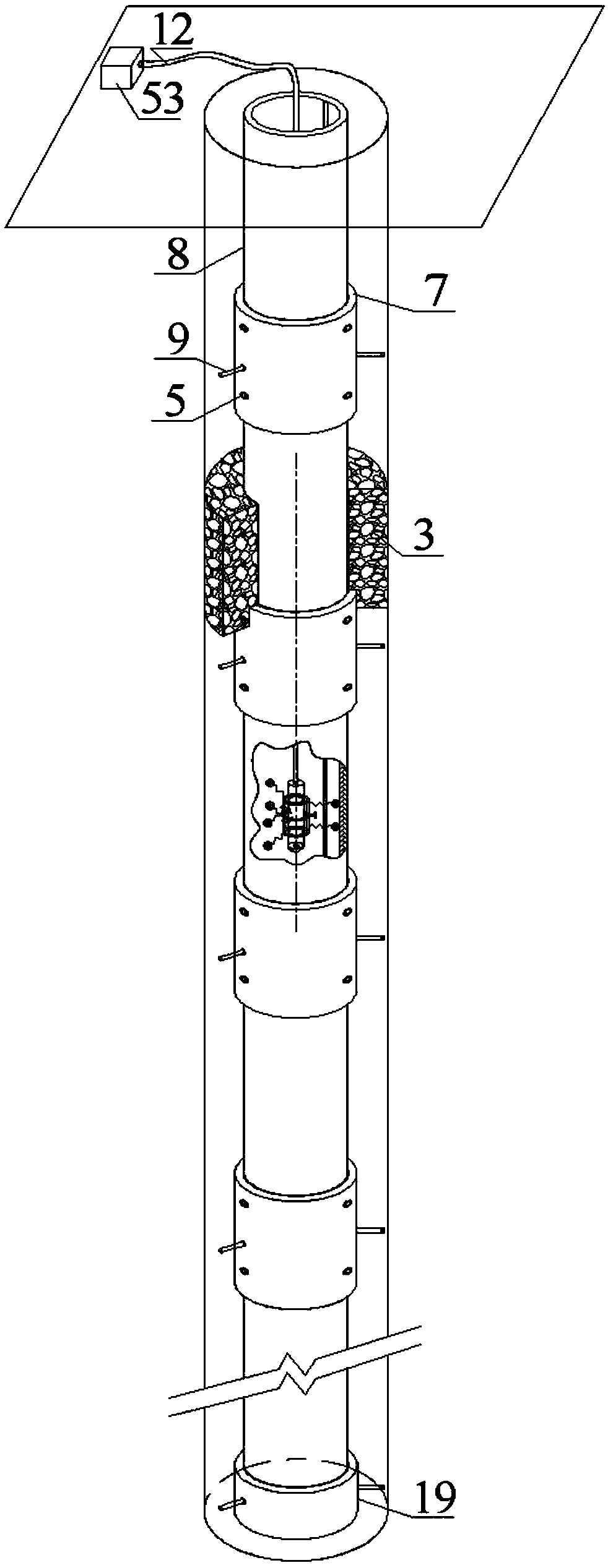
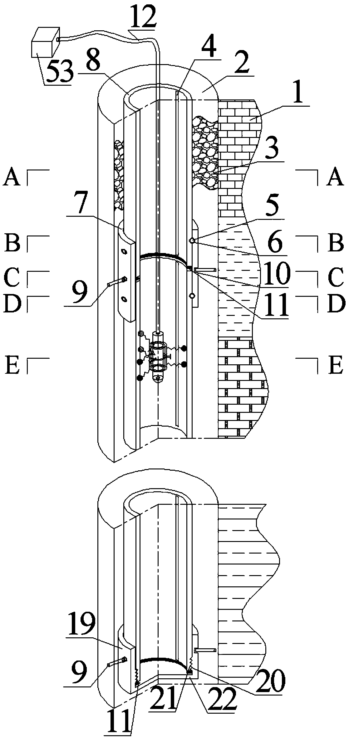
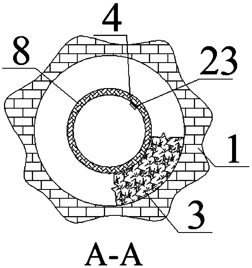
[0056] As shown in the figure, a drilling casing anchorage structure for monitoring cracks in the surrounding rock of the floor includes a floor borehole 2, and the periphery of the floor borehole 2 is the surrounding rock mass 1 of the wall of the borehole. There is a sealed observation tube, and a detection and positioning component is arranged in the sealed observation tube;

[0057] The sealed observation tube includes a plurality of interconnected transparent hollow tubes 8, and the adjacent transparent hollow tubes 8 are connected together by a docking sealing assembly, and the docking sealing assembly includes a docking sleeve 7 and is arranged on both ends of the docking sleeve 7. The two ends of the docking sleeve 7 are respectively set on the ends of the adjacent transparent hollow tube 8, and the two "U"-shaped clips 5 are respectively perpendicula...


PUM


Abstract

The invention discloses a drill hole anchoring structure for monitoring floor surrounding rock fractures and a construction method thereof. Transparent hollow pipes are connected in a butt joint mode section by section through butt joint sealing assemblies and a bottom sealing assembly and then fed into a drill hole; after a gap between the drill hole and the transparent hollow pipes is subjected to grouting anchoring, drill hole surrounding rock fractures at different scale positions on a measuring ruler are recorded through a detecting and positioning assembly. The rock stratum development condition in the drill hole is directly read, and the drill hole anchoring structure has the advantages of being reasonable in integral structural design, easy to construct, safe, stable, low in drilling failure rate, capable of providing clear images, capable of meeting the requirement for repeated observation and the like; the fracture positions and forms on a drill hole grouting body are directly read through the transparent hollow pipes and directly reflect the positions of floor surrounding rock fractures in the drill hole, and compared with traditional distance position data acquired indirectly, errors are greatly reduced; the drill hole in the same position is used for observing the progress of fracture development at different stages, data is real and reliable, and the position and development condition of rock stratum change can be rapidly and precisely obtained.

Description

technical field [0001] The invention relates to a drilling anchorage structure and a construction method for monitoring fissures in the surrounding rock of a floor, belonging to the field of mine support. Background technique [0002] The distribution of my country's coal resources is very regional. At present, about 90% of coal resources are produced in North China coal fields. The severe form of mine water damage has seriously affected the safe production of my country's coal mines and restricted the steady and healthy development of the national economy. The development of coal fields has a great impact on the national economy. development is important. At the same time, the hydrogeological conditions of many coal fields in our country are very complicated, and the coal seam mining process is threatened by various water bodies. The coal reserves threatened by karst water in the main mining areas in the north alone are about 15 billion tons, accounting for 27% of the proven...

Claims


Application Information

Patent Timeline
Patent Type & Authority Patents(China)
IPC IPC(8): E21B23/01E21B47/017
CPCE21B23/01E21B47/017
Inventor 李昂
Owner XIAN UNIV OF SCI & TECH
Why Eureka
Try Eureka