
A detection system and method for monitoring the development of floor cracks in gob-free entry retaining without coal pillars

A detection system, no coal pillar technology, applied in surveying, earthwork drilling, wellbore/well components, etc., can solve problems such as normal construction safety hazards, shallow bottom drilling holes, increase monitoring costs, etc., to avoid problems such as Collapse hole accident occurs, the overall structure design is reasonable, and the effect of overcoming water softening shrinkage

Active Publication Date: 2019-04-09
XIAN UNIV OF SCI & TECH
View PDF5 Cites 3 Cited by
  • Summary
  • Abstract
  • Description
  • Claims
  • Application Information

AI Technical Summary

Problems solved by technology

The gob-side retaining in these two cases will cause the shallow floor drilling to collapse. Even if the protective wall casing is lowered to a certain depth, there will still be collapse holes in the monitoring section (without protective wall casing), and once If a collapsed hole occurs, it is difficult to repair it again. The only way is to re-drill the hole, which is not only time-consuming and labor-intensive, but also more likely to miss the best observation time;
[0006] (2) Coal seam floor strata are generally divided into hard rock strata, soft rock strata, and soft and hard rock strata. Water softening, if the data is not observed in time, the soft rock section of the drill hole may automatically close or collapse in a short period of time, making the drill hole invalid and having to re-drill the drill hole, or even re-drill the drill hole several times, greatly increasing the monitoring Cost; at the same time, the frequent replacement of boreholes results in not only the inability to effectively collect available data, but also no reference comparison for the macroscopic changes of cracks at the same position at different times, and the reliability of the detection results is very low
[0007] (3) Even if the initial borehole peep data can be observed smoothly before the coal seam is mined, as the coal mining face continues to advance, the floor will be mechanically changed due to the support pressure of the coal pillar, resulting in the fracture of the floor rock, resulting in the conventional bare The use of drilling peepers will cause jamming, jamming of the camera, etc., and even damage the camera observation equipment, resulting in certain economic losses
[0008] (4) During the observation period, it is often encountered that there is a large amount of muddy water, sewage, oil-water mixture, suspended solids and air bubbles in the borehole. Even if the borehole is continuously flushed with water injection, it is often impossible to collect effective data, which greatly affects The clarity and authenticity of the observations, and a large number of calculations and evaluations are required to draw a rough conclusion after the data is obtained, and the reliability of the conclusion cannot be guaranteed, that is, the position and development status of the rock formation change cannot be quickly and accurately obtained. Subsequent normal construction brings great potential safety hazards

Method used


Image

  • A detection system and method for monitoring the development of floor cracks in gob-free entry retaining without coal pillars
  • A detection system and method for monitoring the development of floor cracks in gob-free entry retaining without coal pillars
  • A detection system and method for monitoring the development of floor cracks in gob-free entry retaining without coal pillars

Examples


specific Embodiment

[0087] First, prepare a certain proportion of high fluidity non-shrinkage grouting material on the ground for underground use. Large fluidity non-shrinkage grouting material components include inorganic gum base, reinforcement, aggregate, high-efficiency water reducer, expansion agent, water loss reducer, anti-shrinkage agent, defoamer and retarder, and its weight ratio is 45.6% , 6.3%, 42.5%, 0.85%, 3.54%, 0.056%, 0.012%, 0.48%, 0.76%, among which:

[0088] ① The inorganic base is early-strength high-strength Portland cement, the model is 42.5R Portland cement;

[0089] ②The reinforcing agent is high-calcium fly ash with a specification of 200-300 mesh;

[0090] ③ The aggregate is quartz sand, with a particle size distribution of 0-1.25mm, of which 0-0.16mm accounts for 15%, 0.16-0.325mm accounts for 35%, 0.325-0.85mm accounts for 32%, and 0.85-1.25mm accounts for 18%;

[0091] ④The high-efficiency water reducer is a polycarboxylic acid polymer high-efficiency water reducer...


PUM

PropertyMeasurementUnit
particle sizeaaaaaaaaaa
compressive strengthaaaaaaaaaa
strengthaaaaaaaaaa

Abstract

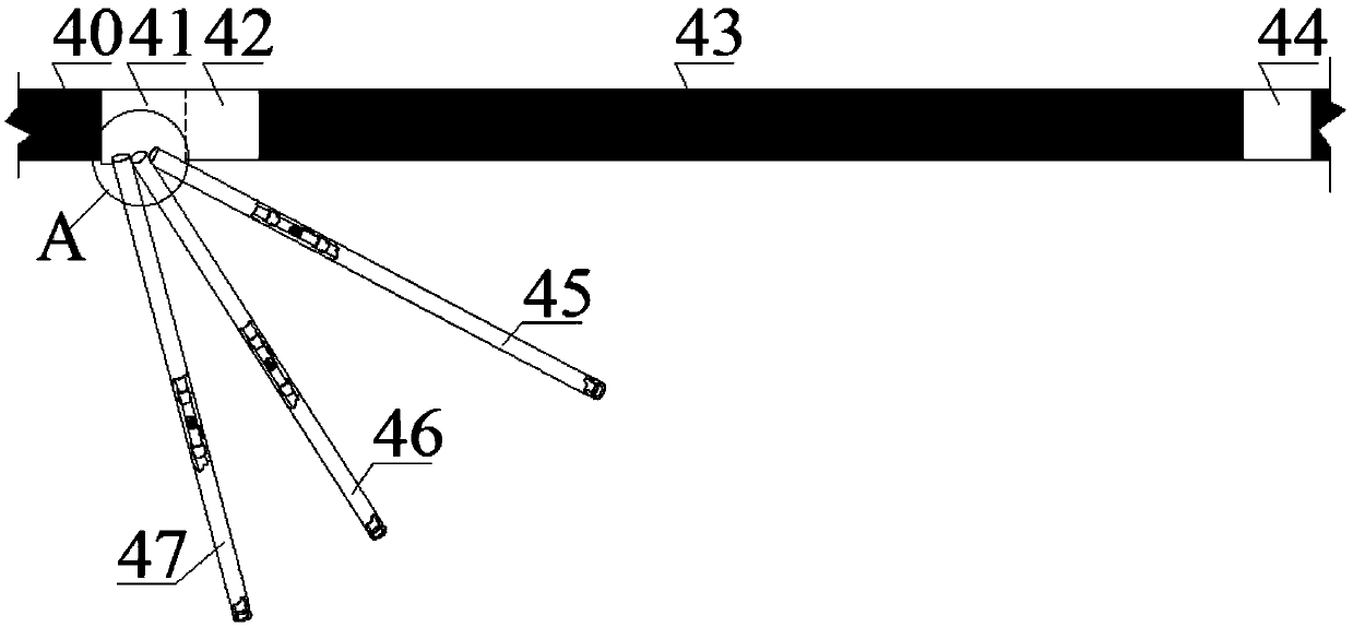
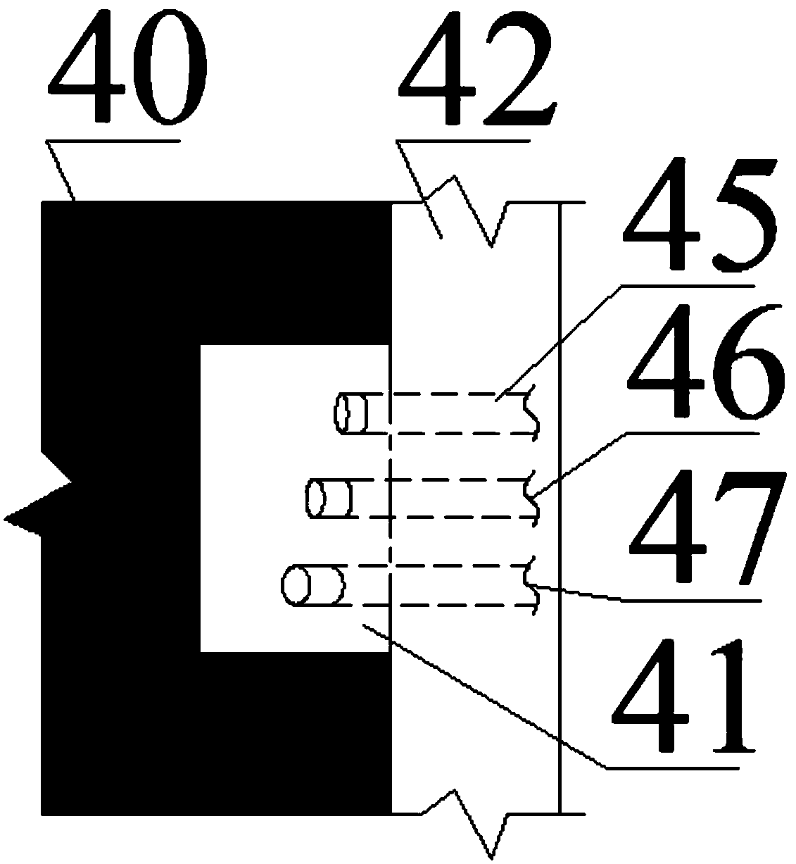
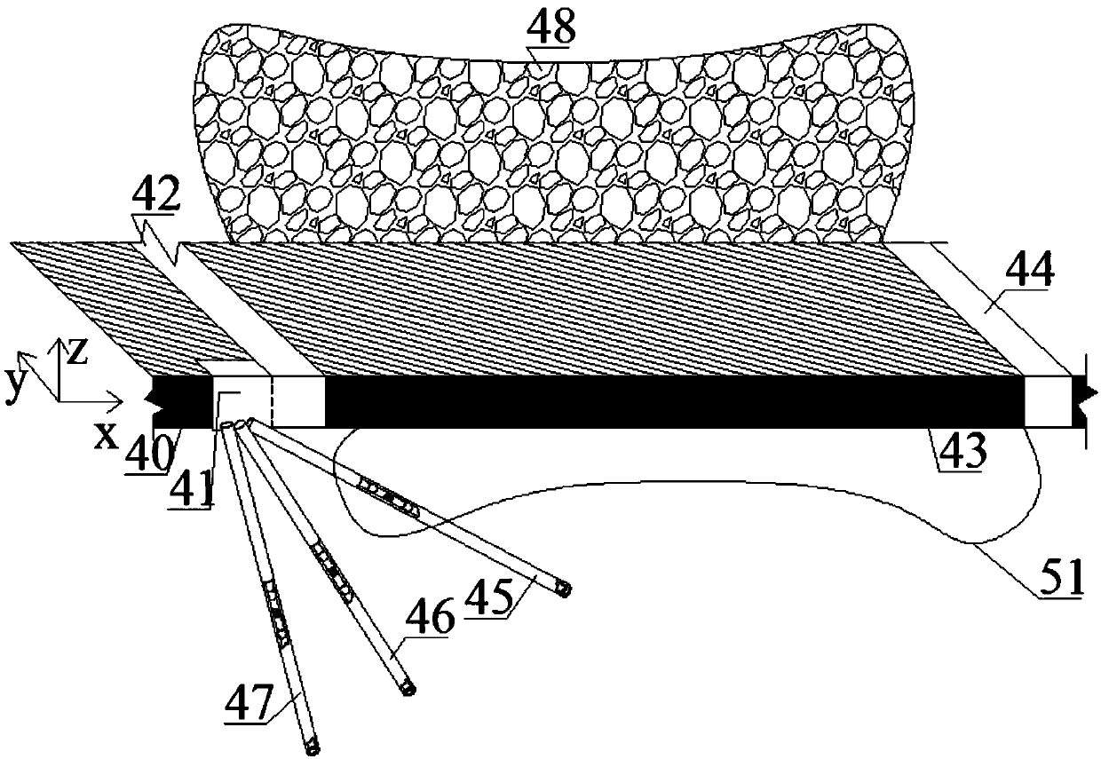
The invention relates to a detection system and a method for monitoring fracture development of a coal pillar-free gob-side entry retaining floor. The method comprises the following steps of chiseling a floor drilling field at one side of the coal pillar-free gob-side entry retaining, drilling in a floor rock layer according to different angles, gradually butting transparent hollow pipe sections by a butting sealing system, and sending into each drilling hole; grouting and anchoring a gap between each drilling hole and the corresponding transparent hollow pipe, enabling a detection positioning assembly to record the fracture of the drilling surrounding rock according to different scales of a measuring tape, performing monitoring tasks on evolution of floor mining failure rule for multiple times in different mining phases until the data is stable, and then finishing the observation. The method has the advantages that the floor small-angle drilling hole, the floor medium-angle drilling hole, and the floor large-angle drilling hole extend from the drilling field to the floor of a to-be-mined coal layer and are distributed in parallel in a stereo way; by observing the fracture condition of adjacent drilling holes in the same time and the fracture condition of the same drilling hole in different coal mining phases, the development state of the plastic failure area of the floor and the development state of the failure area of the floor after the coal bed is mined are determined, so as to provide reliable data reference for safety construction.

Description

technical field [0001] The invention relates to a detection system and method for monitoring the development of cracks in the bottom plate of gob-side entry retention without coal pillars, belonging to the field of mine support. Background technique [0002] The distribution of my country's coal resources is very regional. At present, about 90% of coal resources are produced in North China coal fields. The severe form of mine water damage has seriously affected the safe production of my country's coal mines and restricted the steady and healthy development of the national economy. The development of coal fields has a great impact on the national economy. development is important. At the same time, the hydrogeological conditions of many coal fields in our country are very complicated, and the coal seam mining process is threatened by various water bodies. The coal reserves threatened by karst water in the main mining areas in the north alone are about 15 billion tons, accounti...

Claims


Application Information

Patent Timeline
Patent Type & Authority Patents(China)
IPC IPC(8): E21B47/00E21B47/002E21B33/13C04B28/04C04B28/06
CPCC04B28/04C04B28/06C04B2111/00724C04B2111/70E21B33/13E21B47/00E21B47/002C04B18/08C04B14/06C04B2103/302C04B2103/46C04B2103/50C04B2103/22C04B2103/58
Inventor 李昂
Owner XIAN UNIV OF SCI & TECH
Learn More