Lubrication type harmonic drive

A harmonic reducer and coupling technology, applied in the direction of gear lubrication/cooling, mechanical equipment, transmission parts, etc., can solve the problems of unsatisfactory solid lubricant lubrication effect, damage to the structure of the flexible outer gear cup, etc. The effect of prolonging life and reducing wear

Active Publication Date: 2017-01-11
HIWIN TECH
View PDF10 Cites 0 Cited by
  • Summary
  • Abstract
  • Description
  • Claims
  • Application Information

AI Technical Summary

Problems solved by technology

[0003] In order to achieve the effect of prolonging life and reducing wear, there are different lubrication designs in the prior art. For example, the US7,905,426 patent case mainly allows lubricating oil to be injected into the oil supply of the flexible outer tooth cup through the oil supply path of the rigid inner gear ring In the hole, the wave generator can obtain the lubricating effect, but because the flexible outer tooth cup will continuously produce elastic deformation during the operation process, so the phenomenon of stress concentration is easy to occur at the position of the oil supply hole, resulting in the flexible outer tooth cup Structural damage to the cup
On the other hand, the US6,672,181 patent case is to set a solid lubricant at the contact position between the flexible outer gear cup and the wave generator, but the lubricating effect that the solid lubricant can provide is not ideal

Method used


Image

  • Lubrication type harmonic drive
  • Lubrication type harmonic drive
  • Lubrication type harmonic drive

Examples


Embodiment Construction

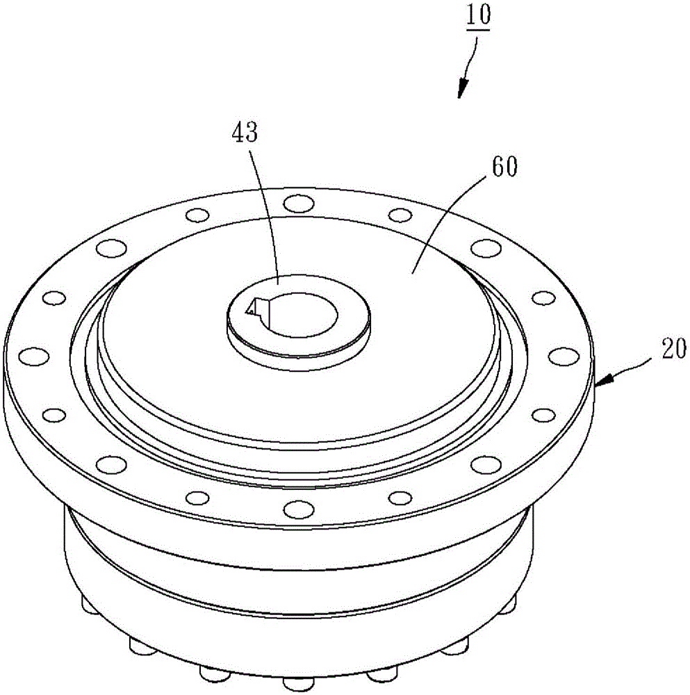
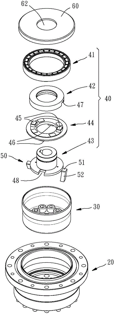
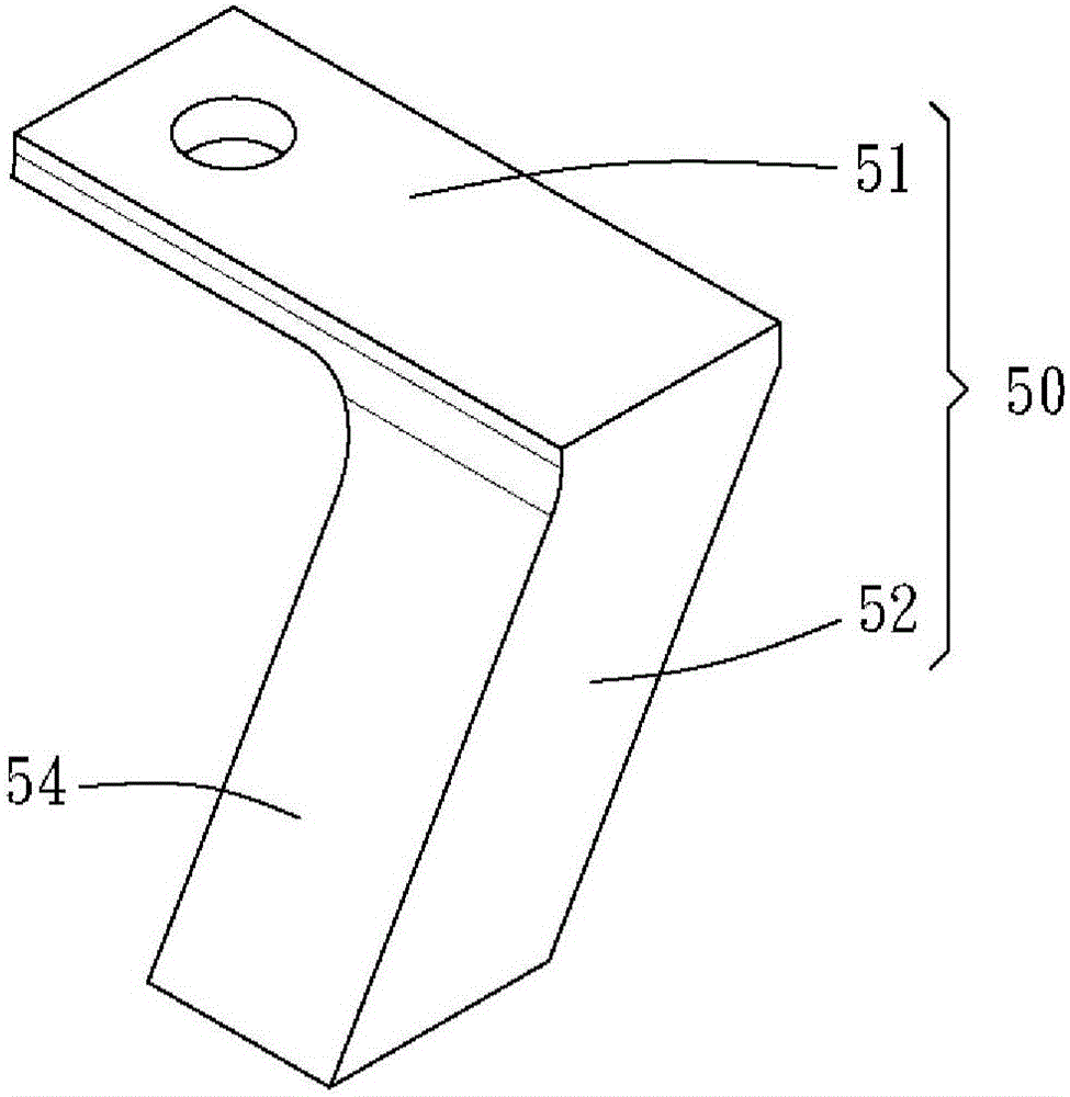
[0031] Please see first figure 1 and figure 2 , the lubricated harmonic reducer 10 of the first embodiment of the present invention includes a rigid inner gear ring 20, a flexible outer tooth cup 30, a wave generator 40, and two spoilers 50, wherein the spoiler 50 As long as there is at least one, and two are the best implementation.

[0032] The flexible outer gear cup 30 is disposed inside the rigid inner gear ring 20 and engages with the rigid inner gear ring 20 together.

[0033] Such as figure 2 and Figure 7 As shown, the wave generator 40 has a bearing 41 , an elliptical wheel 42 , and a coupling 43 . The bearing 41 is set in the flexible outer gear cup 30, the elliptical wheel 42 is set in the bearing 41, the coupling 43 and the elliptical wheel 42 are assembled together through an adapter plate 44, and the two opposite sides of the adapter plate 44 are respectively There are two opposite first protrusions 45 and two opposite second protrusions 46, one side of t...


PUM


Abstract

The invention discloses a lubrication type harmonic drive. The lubrication type harmonic drive comprises a rigid inner gear ring, a flexible outer gear cup, a wave generator and spoilers. The flexible outer gear cup is rotatably engaged to the rigid inner gear ring. The wave generator is provided with a bearing arranged inside the flexible outer gear cup, an oval gear arranged in the bearing, and a coupler connected with the oval gear. The spoilers are connected to the coupler of the wave generator and located in an oil storage space formed between the wave generator and the flexible outer gear cup, the spoilers can be driven by the coupler to drive lubricating oil in the oil storage space towards the wave generator, and accordingly the bearing of the wave generator and the engagement gear face between the rigid inner gear ring and the flexible outer gear cup can obtain a good lubrication effect.

Description

technical field [0001] The invention relates to a harmonic reducer, in particular to a lubricating harmonic reducer. Background technique [0002] The harmonic reducer is a reduction device with a high reduction ratio. In the existing structural configuration, it mainly includes a rigid inner gear ring, a flexible outer tooth cup rotatably arranged in the rigid inner gear ring, and a The wave generator is rotatably installed in the flexible outer tooth cup. When the wave generator is assembled in the flexible outer tooth cup, the flexible outer tooth cup will be pushed by the outer peripheral edge of the wave generator to become an ellipse , thus, when the wave generator is driven by the power source and starts to rotate, the rigid inner gear ring and the flexible outer gear cup can be completely engaged at the long axis of the wave generator, while at the short axis of the wave generator Because there is a difference in the number of teeth between the rigid inner gear ring...

Claims


Application Information

Patent Timeline
Patent Type & Authority Applications(China)
IPC IPC(8): F16H57/04
CPCF16H57/0421F16H57/0472
Inventor 黄柏融蔡宗宪
Owner HIWIN TECH
Why Eureka
Try Eureka