
Permanent-magnet synchronous motor cooling structure

A technology for permanent magnet synchronous motors and cooling structures, applied in cooling/ventilation devices, electrical components, electromechanical devices, etc., can solve problems such as loss, permanent magnet demagnetization, etc., to avoid serious losses, solve cooling problems, and good temperature control effect of effect

Inactive Publication Date: 2017-01-11
GREE ELECTRIC APPLIANCES INC
View PDF6 Cites 5 Cited by
  • Summary
  • Abstract
  • Description
  • Claims
  • Application Information

AI Technical Summary

Problems solved by technology

[0005] In view of this, the present invention provides a permanent magnet synchronous motor cooling structure to solve the cooling problem of motors, especially high-power motors, and avoid serious losses caused by demagnetization of permanent magnets caused by long-term operation of motor rotors in high-temperature environments

Method used


Image

  • Permanent-magnet synchronous motor cooling structure

Examples


Embodiment Construction

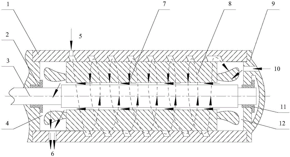
[0025] The invention discloses a cooling structure of a permanent magnet synchronous motor, which is used to solve the cooling problem of the motor, especially a high-power motor, and avoid serious losses caused by demagnetization of the permanent magnet caused by the motor rotor running in a high-temperature environment for a long time.

[0026] The following will clearly and completely describe the technical solutions in the embodiments of the present invention with reference to the accompanying drawings in the embodiments of the present invention. Obviously, the described embodiments are only some, not all, embodiments of the present invention. Based on the embodiments of the present invention, all other embodiments obtained by persons of ordinary skill in the art without making creative efforts belong to the protection scope of the present invention.

[0027] The core improvement points of the permanent magnet synchronous motor cooling structure provided by the embodiment o...


PUM


Abstract

The invention discloses a permanent-magnet synchronous motor cooling structure. The front end of the cavity of a motor is provided with a cooling medium inlet at the joint of a cylinder and a stator. A spiral flow channel is designed between the motor cylinder and the motor stator to cool the outer surface of the motor stator. When cooling medium arrives at the tail end of the motor, as all other parts of the tail end of the motor are sealed, the cooling medium can only pass through an air gap between the stator and a rotor so the cooling medium is forced to cool the outer surface of the motor rotor and the inner surface of the motor stator. Then, the cooling medium enters next container via an air return port at the front end of the motor. As the cooling medium entering the air gap between the motor stator and the rotor has been cooled once, in order to avoid insufficient cooling, a channel of cooling medium is added on the end face of the rear end cover of the motor to enhance the cooling effect. The structure of the scheme is particularly applicable to 500-1500KW high-power permanent-magnet synchronous motors, and can be used in centrifugal compressors, screw compressors, blowers and other similar models.

Description

technical field [0001] The invention relates to the technical field of motors, in particular to a cooling structure of a permanent magnet synchronous motor. Background technique [0002] Permanent magnet synchronous motors have the characteristics of small size, high overall operating efficiency, and high power factor. In recent years, they are often used to drive compressors. Compared with the transmission asynchronous starter motor, the permanent magnet synchronous motor is excited by the permanent magnet in the motor rotor, which can avoid the excitation loss caused by the magnetic field generated by the excitation current, but it also needs to adopt forced heat dissipation measures to take away the heat inside the permanent magnet synchronous motor. Avoid the demagnetization phenomenon caused by the permanent magnet inside the rotor due to long-term high temperature working environment. Especially for high-power motors, the winding current is large, and the heat generat...

Claims


Application Information

Patent Timeline
IPC IPC(8): H02K9/19H02K5/20
CPCH02K9/19H02K5/20
Inventor 蒋楠张治平钟瑞兴蒋彩云刘建飞陈玉辉周义雷连冬刘增岳
Owner GREE ELECTRIC APPLIANCES INC
Learn More