Intelligent lighting system for continuous tunnel group

A lighting system and lighting control system technology are applied in the field of intelligent lighting control systems for continuous tunnel groups, which can solve the problems of light and dark hole effects, inability to transition between lighting brightness and difficult identification of LED light, and achieve the effect of uniform transition.

Active Publication Date: 2017-01-11
JIANGSU CHANGLU ENERGY TECH DEV CO LTD
View PDF9 Cites 12 Cited by
  • Summary
  • Abstract
  • Description
  • Claims
  • Application Information

AI Technical Summary

Problems solved by technology

[0003] At present, the domestic tunnel lighting automatic control system is limited to the automatic control of brightness, and has not yet involved the control of the color temperature of LED lighting fixtures. White light, although it embodies the advantages of high color rendering of LED lighting fixtures in road lighting, but in environments with poor visibility such as heavy fog and rainy days, the cool white LED light is not easy to be recognized by drivers, causing people to have light penetration of LED lighting fixtures. The feeling of poor sex, research shows that 3000K~3500K warm white light has better penetration and recognition under low visibility conditions
[0004] The tunnel lighting system can automatically adjust the brightness of each section of the tunnel through automatic control. However, for continuous tunnel groups, the lighting of the approach roads between tunnels generally adopts the design standards of urban road lighting, which cannot be compared with the lighting of tunnels. The lighting brightness is well connected and transitioned. When the driver drives the vehicle through the continuous tunnel section, due to the uneven transition of the brightness inside the tunnel and the brightness of the approach road outside the tunnel, it is easy to cause the driver to have a light and dark hole effect when entering and exiting the tunnel, which is not conducive to driving safety.

Method used


Image

  • Intelligent lighting system for continuous tunnel group
  • Intelligent lighting system for continuous tunnel group
  • Intelligent lighting system for continuous tunnel group

Examples


Embodiment Construction

[0028] In order to make the technical solutions and advantages of the present invention more clear, the technical solutions in the embodiments of the present invention are clearly and completely described below in conjunction with the drawings in the embodiments of the present invention:

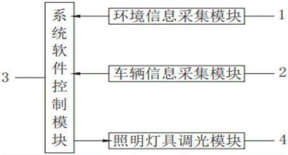
[0029] Such as figure 1 The continuous tunnel group intelligent lighting system shown includes an environmental information collection module 1 , a vehicle information collection module 2 , a software system control module 3 , and a lighting fixture dimming module 4 . Environmental information collection module 1 collects brightness and visibility outside the tunnel, vehicle information collection module 2 collects traffic volume and vehicle speed, and environmental information collection module 1 and vehicle information collection module 2 transmit the monitored data information to software system control module 3 After the software system control module 3 receives the environmental informa...


PUM


Abstract

The invention discloses a tunnel lighting control system. The system comprises the steps of receiving environmental information parameters and a vehicle information parameter, calculating brightness required by each section in tunnels, judging whether to adjust color temperatures according to the environment visibility and transmitting calculated brightness values and color temperature values of the sections in the tunnels and approach sections outside holes to a lighting lamp dimming module; and receiving a dimming instruction sent by a software system control module by the lighting lamp dimming module, controlling LED lighting lamps of the sections in the tunnels to be adjusted to the brightness values and color temperature values set by the software system control module and achieving uniform transition of the lighting brightness between a last exit section and a next entrance section. The system control mode is simple and convenient; the brightness and the color temperatures of the sections in the tunnels in the holes of tunnel sections in the continuous tunnel group and the approach sections outside the holes are intelligently controlled according to different environmental parameters and traffic flow conditions; and the uniform transition of the lighting brightness of the lamps of the tunnel sections in the continuous tunnel group is ensured.

Description

technical field [0001] The invention relates to the field of tunnel lighting control, more specifically, to a continuous tunnel group intelligent lighting control system. Background technique [0002] Nowadays, tunnel lighting control methods mainly include manual control, sequential control and automatic dimming control. Manual control requires a special person to be responsible for lighting management. According to environmental factors such as different time periods and weather, the number and mode of lighting switches are subjectively determined. This control method leads to high operating costs and extremely low scientific intelligence; the timing control adjusts the brightness of the lamps according to time periods during the day and night, and this method does not consider the actual brightness requirements in the tunnel due to factors such as brightness outside the tunnel and traffic flow. Automatic control is to control the switch of each lighting circuit accordi...

Claims


Application Information

Patent Timeline
Patent Type & Authority Applications(China)
IPC IPC(8): H05B33/08H05B44/00
CPCH05B45/10
Inventor 张璟刘强张宁波胡瑶瑶
Owner JIANGSU CHANGLU ENERGY TECH DEV CO LTD
Why Eureka
Try Eureka