Clamp spring conveying press-in structure

A circlip and indenter technology, applied in the field of circlip handling and pressing into the structure, can solve the problems of low installation efficiency, low qualified rate of finished products, low production capacity, etc. The effect of efficiency

Active Publication Date: 2017-01-18
昆山嘉斯特自动化技术有限公司
View PDF6 Cites 15 Cited by
  • Summary
  • Abstract
  • Description
  • Claims
  • Application Information

AI Technical Summary

Problems solved by technology

[0002] Bearing and rotor assembly has always been a labor-intensive industry. Due to the particularity of the product, automatic production has not been realized. Due to the poor uniformity and irregularity of the incoming materials of the product parts, a large amount of labor is required to locate the production product and identify the direction during the production assembly process. , leading to low production capacity, backward production technology and low pass rate of finished products
At the same time, with the current huge labor cost and the expansion of the labor gap and other factors, the cost of bearing rotor production and assembly has risen sharply. It is assembled by hand, resulting in a large amount of labor costs. There is an urgent need to realize automated production, high production capacity, and quality products. High-efficiency automation equipment to support
Moreover, the assembly of the existing bearings and circlips requires workers to manually transport and position the circlips, which makes the installation of the circlips time-consuming and laborious, and the installation efficiency is low

Method used


Image

  • Clamp spring conveying press-in structure
  • Clamp spring conveying press-in structure

Examples


Embodiment Construction

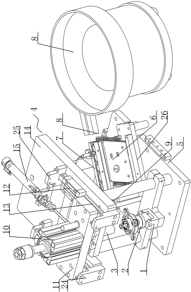
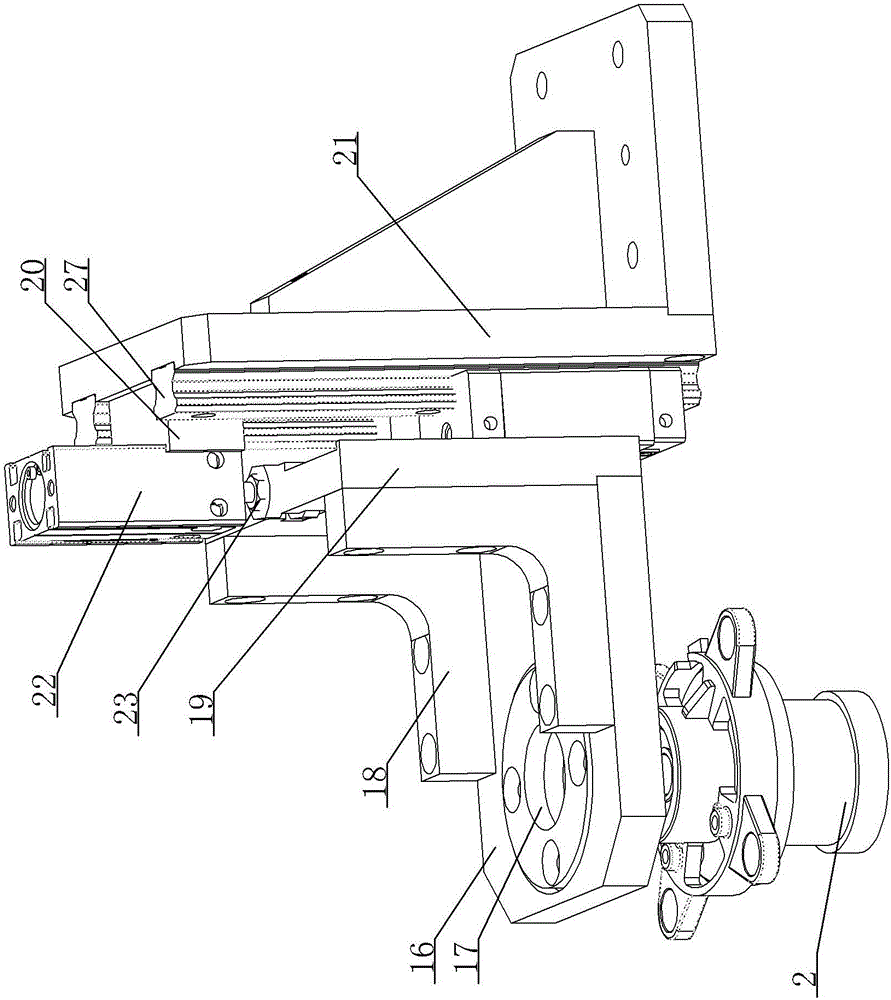
[0015] A kind of circlip handling press-in structure, see figure 1 , figure 2 : It includes a jig tray 1, a jig 2 is fixed on the jig tray 1, the jig 2 is used for positioning the bearing, an indenter 3 is arranged above the jig 2, and a magnet is built in the indenter 3, and the jig tray 1 Supported on the bottom plate 5 of the bracket 4, the bottom plate 5 of the bracket 4 is provided with a direct vibration machine 6, and the upper end surface of the direct vibration machine 6 is fixed with a linearly arranged circlip flow channel 7, and the input end of the circlip flow channel 7 Connect the discharge port of the feeding vibrating plate 8, there are circlips stacked in the feeding vibrating plate 8, the product arrival sensor 9 is arranged towards the output end of the circlip flow channel 7, the upper part of the pressure head 3 is fixed on the circlip and pressed into The piston ends of the upper and lower cylinders 10 are pressed into the bases of the upper and lower ...


PUM


Abstract

The invention provides a clip-spring conveying press-in structure, which can quickly and accurately transport the circlip to the corresponding position of the bearing and quickly press-fit, such that the installation efficiency is improved, the installation is time-saving and labor-saving. The invention relates to a fixing device for positioning bearing, which is used for locating bearing and is provided with a pressure head on the upper part of the jig, and a vertical vibration machine is arranged on the bottom plate of the bracket. The base plate of the jig is arranged on the bottom plate of the bracket. The upper end surface of the vertical vibration machine is arranged with a straight-line clamping spring flow path, and the input end of the vertical vibration machine is connected with the discharging port of the feeding reel, wherein the input end of the upper charging reel is arranged with a clamping spring, and the product-in-place inductor is arranged toward the output end of the clamping spring flow path, the upper part of the pressure head is fixed to the piston end of the upper and lower cylinder, and the base of the upper and lower cylinder is fixed to the fixing plate of the upper and lower cylinder, and the bottom slider of the upper and lower cylinder fixing plates is embedded in two lines.

Description

technical field [0001] The invention relates to the technical field of bearing assembly, in particular to a clamp spring transport and press-in structure. Background technique [0002] Bearing and rotor assembly has always been a labor-intensive industry. Due to the particularity of the product, automatic production has not been realized. Due to the poor uniformity and irregularity of the incoming materials of the product parts, a large amount of labor is required to locate the production product and identify the direction during the production assembly process. , leading to low production capacity, backward production technology and low pass rate of finished products. At the same time, with the current huge labor cost and the expansion of the labor gap and other factors, the cost of bearing rotor production and assembly has risen sharply. It is assembled by hand, resulting in a large amount of labor costs. There is an urgent need to realize automated production, high produc...

Claims


Application Information

Patent Timeline
Patent Type & Authority Applications(China)
IPC IPC(8): B23P19/08B23P19/00
CPCB23P19/006B23P19/084
Inventor 刘连桥李涛王翔王庭
Owner 昆山嘉斯特自动化技术有限公司
Why Eureka
Try Eureka