
Pneumatic control system for fire door

A pneumatic control system and technology for fire doors, applied in fire doors, fluid pressure actuators, servo motors, etc., can solve the problems that electrical circuits and electrical components are difficult to guarantee normal use, and are not suitable for electrical systems. Good safety protection effect, reliable effect

Active Publication Date: 2017-01-18
WUXI HUATONG PNEUMATIC MFG
View PDF6 Cites 0 Cited by
  • Summary
  • Abstract
  • Description
  • Claims
  • Application Information

AI Technical Summary

Problems solved by technology

However, there are restrictions on the use of electrical circuits. When a fire occurs, it is difficult to guarantee the normal use of electrical circuits and electrical components. In addition, it is not suitable for the use of electrical systems in some flammable and explosive occasions.

Method used


Image

  • Pneumatic control system for fire door

Examples


Embodiment Construction

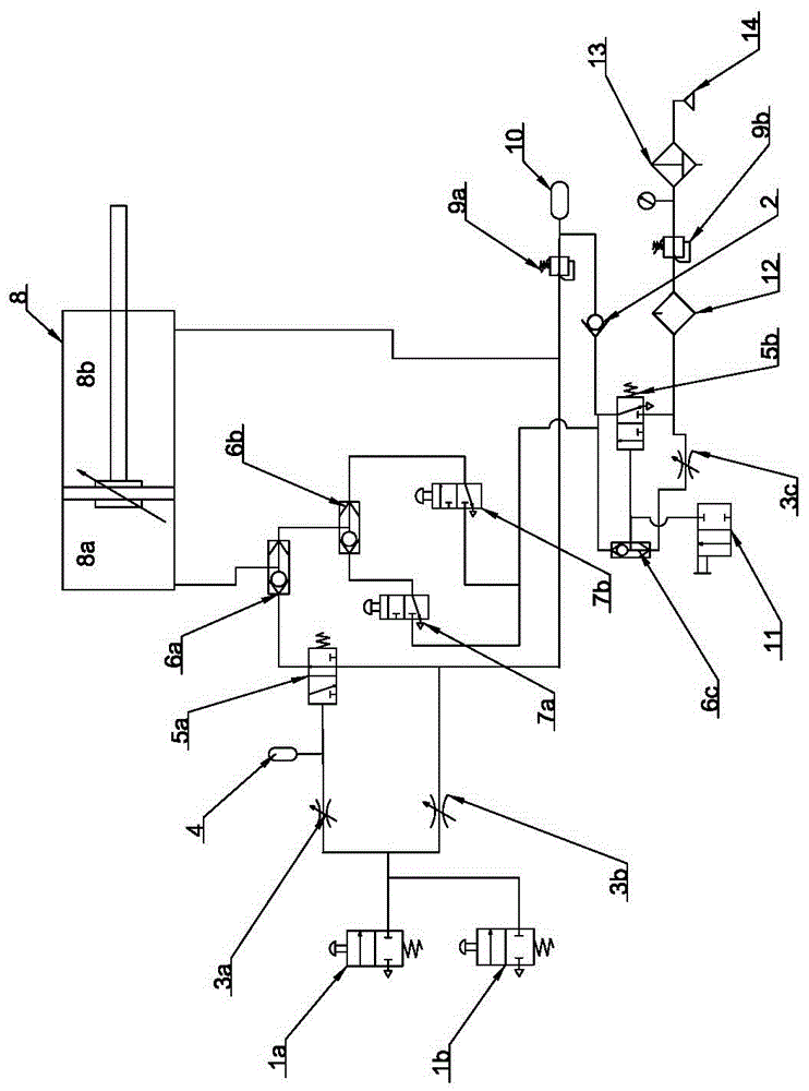
[0011] Such as figure 1 Shown is a pneumatic control system for a fire door, which includes a cylinder 8 for driving the fire door switch, a normally open door valve 7a and a normally open door valve 7b installed on the inside and outside of the door, respectively, installed on the door The inner and outer door opening button 1a and door opening button 2 1b, the air source 14 and the gas storage tank 10, the air source 14 is connected to the air-controlled reversing valve 5b and the air-controlled reversing valve after the filter 13, the pressure reducing valve 9b and the oil and gas separator 12 The inlet end of the throttle valve 1 3c, the air control reversing valve 5b is an air control two-position three-way valve, the outlet end of the air control reversing valve 5b is divided into four ways, the first way is connected to one of the shuttle valve 6C Inlet, the second path is connected to the gas tank 10 through the one-way valve 2, and the remaining two paths are respectiv...


PUM


Abstract

The invention discloses a pneumatic control system for fire doors in the field of fire doors. The air source is connected to a pneumatic operated directional valve # 1 and a throttle valve #1, with the outlet of the pneumatic operated directional valve #1 connected toshuttle valve #1, air collector and two normally opened door opening valve; with the outlet of shrottle valve #1 connected to temperature-sensitive relief valve via shuttle valve #1; the outlet of shuttle valve #1 connected the aircontrol end of the pneumatic operated directional valve; with the outlet of the air collector conneted to one end of the air cylinder, throttle valve #2 and pneumatic operated directional valve # via reducing valve #2; with the outlet of the pneumatic operated directional valve #2 connected with the shuttle valve #3, the outlets of normally opened door opening valve connected to the inlets of shuttle valve #2 respectively, and the outlet of shuttle valve#2 connected to the inlet of the shuttle valve #3, and the outlet of shuttle valve #3 connected to the other end of the cylinder; the gas control mouth of pneumatic operated directional valve #2 connected to the outlet that gas holds unit and choke valve #3, and the outlet of choke valve #2 is connected with the import of choke valve #3, and the two buttons for opening the door are connected between the outlet of choke valve #2 and the import of choke valve #3. In case of fire, the fire door is closed automatically and has good safety protection.

Description

Technical field [0001] The invention relates to a pneumatic control and execution system for controlling a fire door. It is suitable for fire partition doors or other occasions where it is inconvenient to use the control door switch of the electric control system. Background technique [0002] The fire doors in the prior art generally use electric, electric or pneumatic control systems to control the opening and closing of the door. Usually, the electric system uses electric signals to control electric actuators or solenoid valves to control pneumatic actuators to open and close the doors. Smoke sensors, etc. obtain fire or temperature change signals, so that the control system performs corresponding control based on these signals. However, there are restrictions on the use of electrical wiring. When a fire occurs, it is difficult to ensure the normal use of electrical wiring and electrical components. In addition, it is not suitable for use in electrical systems in some flammab...

Claims


Application Information

Patent Timeline
Patent Type & Authority Applications(China)
IPC IPC(8): F15B11/08F15B13/02E06B5/16
CPCE06B5/16F15B11/08F15B13/02
Inventor 唐国祥魏文龙
Owner WUXI HUATONG PNEUMATIC MFG
Learn More