High-precision interference type optical fiber gyroscope temperature drift error model optimizing method

A technology of fiber optic gyroscope and error model, which is applied in the direction of Sagnac effect gyroscope, gyroscope/steering sensing equipment, instrument, etc., can solve the problem that the output data of the interferometric fiber optic gyroscope cannot be guaranteed, and the interferometric method cannot be accurately estimated. Problems such as the temperature drift error of the fiber optic gyroscope, to achieve the effect of improving accuracy and real-time performance, improving dynamic performance and steady-state performance, and improving versatility

Inactive Publication Date: 2017-01-18
HARBIN ENG UNIV
View PDF5 Cites 14 Cited by
  • Summary
  • Abstract
  • Description
  • Claims
  • Application Information

AI Technical Summary

Problems solved by technology

However, the basic model of the interferometric fiber optic gyroscope’s temperature drift error does not have the ability to accurately estimate the temperature drift error of the interferometric fiber optic gyroscope, and thus cannot guarantee the accurate and stable output data of the interferometric fiber optic gyroscope, and the strapdown fiber optic gyroscope The navigation system works stably

Method used


Image

  • High-precision interference type optical fiber gyroscope temperature drift error model optimizing method
  • High-precision interference type optical fiber gyroscope temperature drift error model optimizing method
  • High-precision interference type optical fiber gyroscope temperature drift error model optimizing method

Examples


Embodiment Construction

[0042] The present invention is described in more detail below in conjunction with accompanying drawing example:

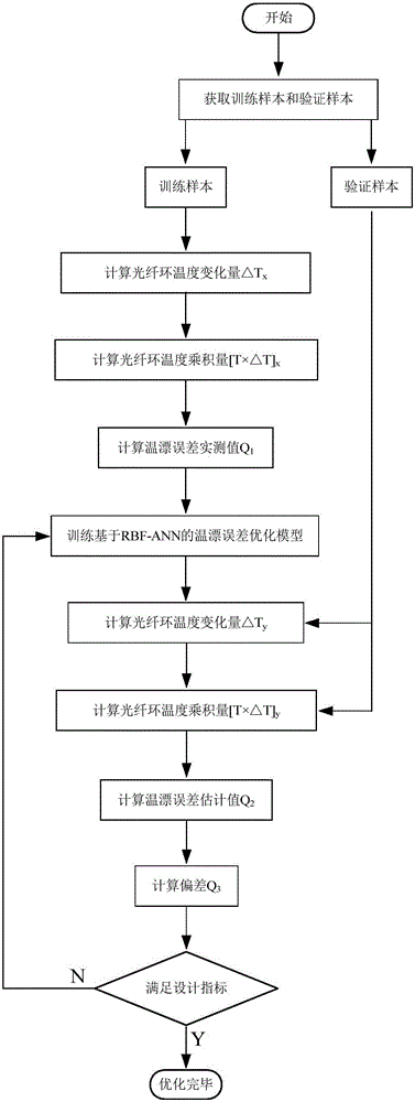
[0043] to combine Figure 1-7 , the present invention includes the following processes:

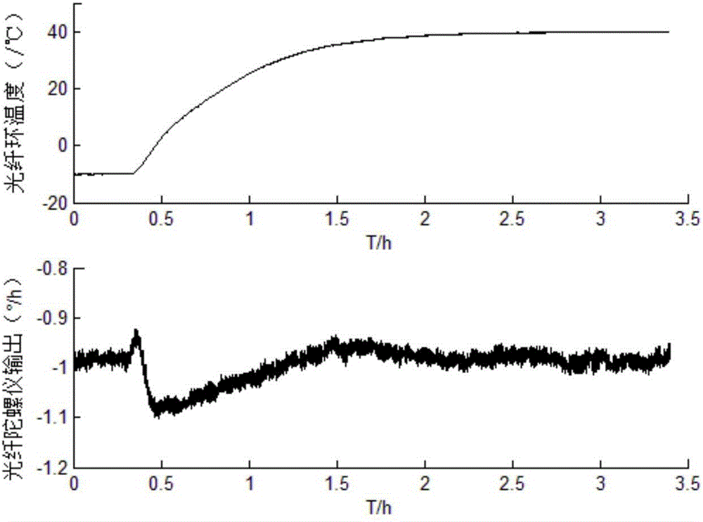
[0044] Step 1. Complete the relevant preparatory work, set up the test environment, install the interferometric fiber optic gyroscope in the high-low temperature box (SET-Z-021UF) integrated with a high-precision turntable, and ensure that the high-low temperature box and turntable can work normally. The fiber optic gyroscope can output normally. A temperature sensor is installed at the fiber ring of the interferometric fiber optic gyroscope, and the real-time temperature value of the fiber ring is measured by a high-precision temperature measurement system with a temperature measurement accuracy of ±0.05°C and a data recording frequency of 1 Hz, and the temperature value of the fiber ring is recorded in real time.

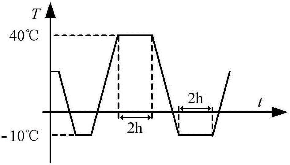
[0045] Step 2, use the temperature rise and fall experiment...


PUM


Abstract

The invention aims to provide a high-precision interference type optical fiber gyroscope temperature drift error model optimizing method. According to the method, optical fiber ring temperature product quantity T*delta T, optical fiber ring temperature T and optical fiber ring temperature variable quantity delta T jointly serve as optimal input quantities of an interference type optical fiber gyroscope temperature drift error basic model, and an interference type optical fiber gyroscope temperature drift error optimization model is realized by adopting RBF-ANN; a temperature drift error measured value is obtained by a temperature increasing and reducing test, a temperature drift error estimated value is obtained by estimating an optimization model, and the precision of the optimized model is verified by comparing the temperature drift error measured value and the estimated valve. According to the method, the adopted optimal input quantities are more integral, the temperature drift error model is described more precisely, the accuracy, the real-time property and the universality of interference type optical fiber gyroscope temperature drift error estimation are improved, and the stability and the reliability of output data of the interference type optical fiber gyroscope are guaranteed.

Description

technical field [0001] The invention relates to a method for acquiring the temperature drift error of an optical fiber gyroscope. Background technique [0002] Optical gyroscopes are the core components widely used in medium and high-precision strapdown inertial navigation systems, mainly including interferometric fiber optic gyroscopes and laser gyroscopes. Compared with laser gyroscopes, interferometric fiber optic gyroscopes have the advantages of fast start-up, low cost, high reliability, and good structural stability, and there is no latch-up effect, and can accurately measure small angular velocities. Therefore, interferometric fiber optic gyroscopes are increasingly being used in strapdown inertial navigation systems. [0003] Ambient temperature is an important factor affecting the accuracy characteristics of interferometric fiber optic gyroscopes. The reason is that the change of ambient temperature will affect the physical characteristics of the fiber optic ring,...

Claims


Application Information

Patent Timeline
Patent Type & Authority Applications(China)
IPC IPC(8): G01C19/72G01C25/00
CPCG01C19/72G01C19/721G01C25/00
Inventor 程建华齐兵刘萍陈岱岱于东伟蒋国桉刘柱康瑛瑶费再慧董楠楠
Owner HARBIN ENG UNIV
Why Eureka
Try Eureka