Magnetic valve type controllable reactor control system sampling circuit
A technology of control system and sampling circuit, applied in the field of electric power system, can solve the problems of voltage and current sampling thyristor trigger signal, etc., and achieve the effect of good real-time and accuracy
- Summary
- Abstract
- Description
- Claims
- Application Information
AI Technical Summary
Problems solved by technology
Method used
Image


Examples
Embodiment Construction
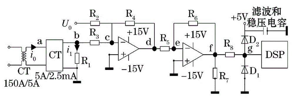
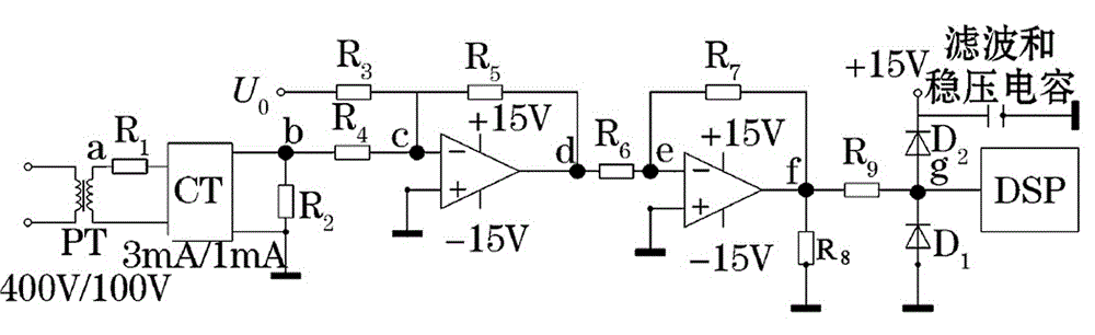
[0014] Such as figure 1 As shown, it is a block diagram of the overall structure of the sampling circuit of the control system of a magnetic valve type controllable reactor invented. In the figure, it includes three phases A, B and C on the bus side, load, magnetic valve type controllable reactor MCR, signal sampling and conditioning circuit; the key points of its structure are: the signal sampling and conditioning circuit is connected to ADSP-BF506F, the ADSP-BF506F communicates with PC host computer through serial communication RS232 / 422 or RS485, the I / O port of ADSP-BF506F is connected with magnetic valve type controllable reactor MCR, and communicates through optical fiber; the bus side A, The three phases of B and C are connected with a voltage transformer PT and a current transformer CT, and the first-stage voltage transformer PT and the first-stage current transformer CT are connected with a signal sampling and conditioning circuit, and the signal sampling and conditio...
PUM
 Abstract
Description
Claims
Application Information
 - R&D
- Intellectual Property
- Life Sciences
- Materials
- Tech Scout
- Unparalleled Data Quality
- Higher Quality Content
- 60% Fewer Hallucinations
Browse by: Latest US Patents, China's latest patents, Technical Efficacy Thesaurus, Application Domain, Technology Topic, Popular Technical Reports.
© 2025 PatSnap. All rights reserved.Legal|Privacy policy|Modern Slavery Act Transparency Statement|Sitemap|About US| Contact US: help@patsnap.com