

A system for testing the long and short distance dynamic accuracy index of laser equipment
A dynamic accuracy and index testing technology, which is applied in the direction of optical instrument testing, radio wave measurement system, machine/structural component testing, etc., can solve problems such as the inability to test dynamic accuracy indicators
Active Publication Date: 2013-02-13
NO 27 RES INST CHINA ELECTRONICS TECH GRP
View PDF0 Cites 22 Cited by
- Summary
- Abstract
- Description
- Claims
- Application Information
AI Technical Summary
Problems solved by technology
The purpose of the present invention is to provide a system for testing the dynamic accuracy index of the laser equipment at a distance, which can solve the problem that the dynamic accuracy index of the laser equipment cannot be tested under the condition of high speed and large dynamic distance range
Method used
View moreImage
Smart ImageViewing Examples

Examples
Embodiment Construction
Login to View More PUM
 Abstract
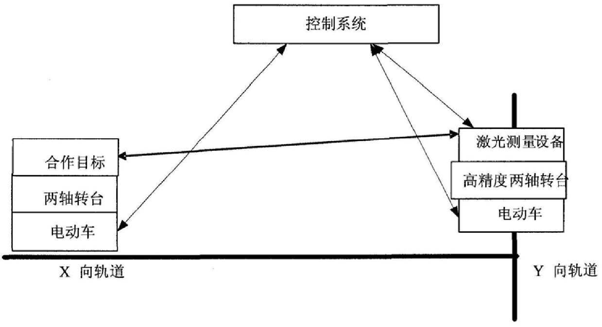
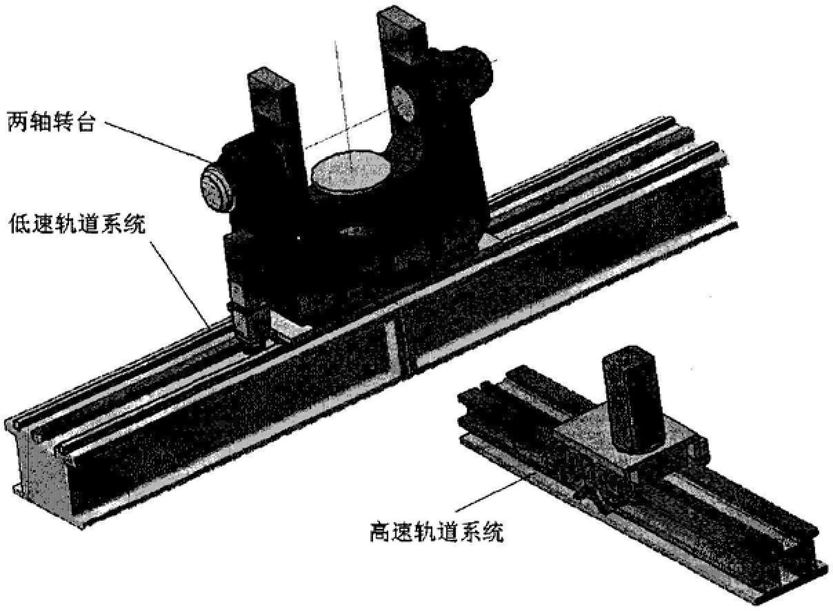
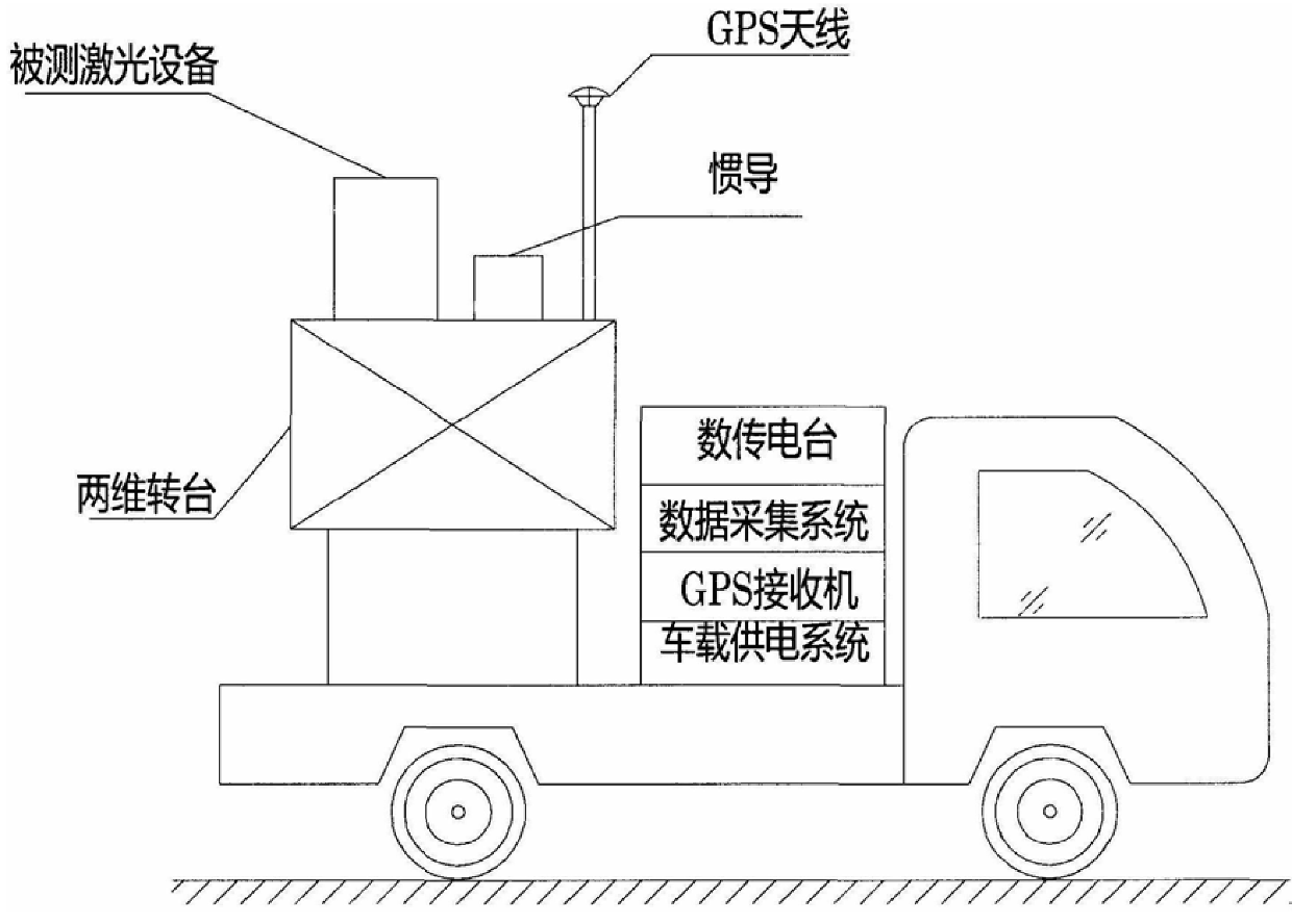
The present invention provides a system for testing the dynamic accuracy index of laser equipment at a distance, which is characterized in that the short-distance dynamic accuracy index test subsystem moves the measured laser The six-degree-of-freedom motion simulation of the equipment relative to the cooperative target in space is used to measure and calibrate the laser equipment under test; the long-distance dynamic accuracy index test subsystem includes the equipment vehicle, the target vehicle and two sets of vehicle-mounted differential GPS systems. A set of GPS receivers constitutes a double differential GPS system, which measures the relative distance between the equipment vehicle and the target vehicle in real time with high precision; the two-dimensional turntable installed on the roof of the equipment vehicle dynamically simulates the movement of the measured laser equipment relative to the cooperative target in space , so that the six-degree-of-freedom movement of the laser device under test relative to the cooperative target is simulated in space, and the laser device under test is measured and calibrated. The invention can solve the problem that the dynamic accuracy index of the laser equipment cannot be tested under the conditions of high speed and large dynamic distance range.
Description
A system for testing the long- and short-distance dynamic accuracy index of laser equipment technical field The invention relates to the field of measuring and testing equipment for laser equipment, in particular to a system for testing the dynamic accuracy index of the laser equipment at a distance. Background technique At present, the laser tracker can be used to realize the dynamic accuracy test of the laser equipment. The method is accomplished using a laser tracker and a cooperating target (target ball). During the test, the laser tracker is installed as close as possible to the laser equipment under test, and the target ball is placed on the target to be tested. The laser tracker first stably tracks the target ball, and then the device under test and the target to be tested The laser tracker system moves as a whole, and according to the coordinates of the laser tracker test output relative to the target ball, the time interval of the test points, etc., through geome...
Claims
Login to View More Application Information
Patent Timeline
 IPC IPC(8): G01M11/00G01S17/88
Inventor薛海中张清源张东晓赵春生屈恒阔李勇周莹左向科邢旭东吴淦华李鹏邓全司光芙马京川
OwnerNO 27 RES INST CHINA ELECTRONICS TECH GRP