A high-speed clock signal phase detection circuit
A high-speed clock, reference clock signal technology, applied in the direction of electrical components, automatic power control, etc., can solve the problem of difficult to meet the requirements of phase detection
Inactive Publication Date: 2013-09-11
LEIHUA ELECTRONICS TECH RES INST AVIATION IND OF CHINA
View PDF0 Cites 0 Cited by
- Summary
- Abstract
- Description
- Claims
- Application Information
AI Technical Summary
Problems solved by technology
This phase detection circuit can meet the requirements when the clock frequency is less than 300MHz; but for higher frequency clock signals, it is difficult to meet the phase detection requirements
Method used
View moreImage
Smart ImageViewing Examples

Examples
Embodiment Construction
Login to View More PUM
 Abstract
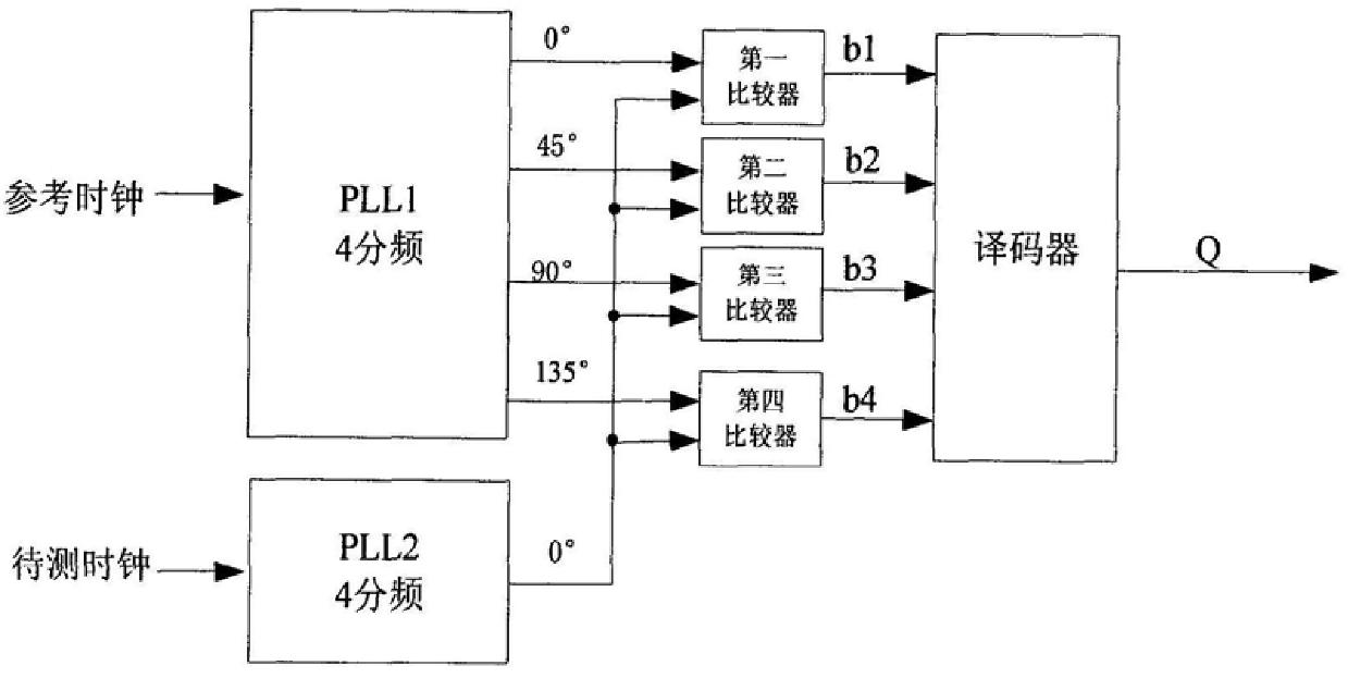
The invention belongs to high-speed digital signal processing technology, and relates to the improvement of clock phase detection circuit. It consists of the first phase-locked loop circuit PLL1, the second phase-locked loop circuit PLL2, four comparators and a decoder. The two phase-locked loop circuits respectively form two four-frequency division circuits, and the 0°, 45°, 90° and 135° four-frequency division reference clock signal output terminals of the first phase-locked loop circuit PLL1 are compared with the first to fourth The first input end of the device is connected, and the 0° four-frequency division clock signal output end of the second phase-locked loop circuit PLL2 is connected with the second input end of the first comparator to the fourth comparator respectively; The output terminal b1 to the output terminal b4 of the fourth comparator are respectively connected to the first to fourth input terminals of the decoder. The invention satisfies the requirement of phase detection of high-frequency clock signal above 300MHz.
Description
A high-speed clock signal phase detection circuit technical field The invention belongs to high-speed digital signal processing technology, and relates to the improvement of clock phase detection circuit. Background technique As the key factor of high-speed digital signal processing circuit, the clock signal has an extremely important influence on the accuracy and stability of the whole system. However, the traditional design is difficult to meet the synchronization requirements of multiple high-speed clock signals. Generally, the phase difference between the two clock signals should be detected by a phase detector circuit, and then the synchronization process should be performed. A common phase detection circuit uses a comparator, and uses the reference clock as the reference clock signal to judge the phase relationship between the clock under test and the reference clock. If the output of the comparator is 1, it means that the clock under test is ahead of the reference c...
Claims
Login to View More Application Information
Patent Timeline
 IPC IPC(8): H03L7/085
Inventor 陆珺赵军王利华
Owner LEIHUA ELECTRONICS TECH RES INST AVIATION IND OF CHINA
Features
- R&D
- Intellectual Property
- Life Sciences
- Materials
- Tech Scout
- Unparalleled Data Quality
- Higher Quality Content
- 60% Fewer Hallucinations
Learn More Browse by: Latest US Patents, China's latest patents, Technical Efficacy Thesaurus, Application Domain, Technology Topic, Popular Technical Reports.
© 2025 PatSnap. All rights reserved.Legal|Privacy policy|Modern Slavery Act Transparency Statement|Sitemap|About US| Contact US: help@patsnap.com