A Fast Cutting Method of Hinge Point Shaft

A rapid cutting and hinge point technology, which is applied in metal processing, metal processing equipment, manufacturing tools, etc., can solve the problem of large matching size between the pin shaft and the hinge point hole sleeve of the structural part, difficult to disassemble the pin shaft, and long waiting period for replacement parts And other issues

Active Publication Date: 2018-06-26
XUZHOU HEAVY MASCH CO LTD
View PDF5 Cites 0 Cited by
  • Summary
  • Abstract
  • Description
  • Claims
  • Application Information

AI Technical Summary

Problems solved by technology

Due to the damage or corrosion of the surface of the ground pin, and the matching size between the pin and the hinge hole sleeve of the structural part is very large, it is difficult to disassemble the pin by purely mechanical methods such as knocking and pulling. Pins take a week or more to remove
[0008] 2. It is a destructive disassembly method to disassemble the pin shaft by cutting the hinge point hole of the structural part. The disassembled structural part needs partial maintenance before it can be used, or even be scrapped directly. This disassembly method is very costly and waits for replacement parts The period is also very long

Method used


Image

  • A Fast Cutting Method of Hinge Point Shaft

Examples


Embodiment Construction

[0028] The present invention will be specifically introduced below in conjunction with the accompanying drawings and specific embodiments.

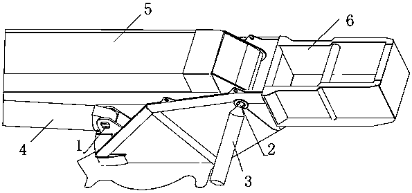
[0029] A fast cutting method of hinge point shaft:

[0030] Before cutting, prepare for the protection of operators and vehicles. Personnel protection requires comprehensive heat insulation protection for the head, face, arms, torso, legs, and feet.

[0031] The operator holds the cutting gun and aligns the oxygen melting rod at the center of the pin shaft end, gently holds the handle of the cutting tool without current, and supplies a small amount of oxygen. Another operator ignites with an oxyacetylene flame, and when the oxygen fusion rod starts to burn spontaneously, removes the oxyacetylene flame, and the operator increases the oxygen supply to make the oxygen fusion rod burn more intensely.

[0032] The operator aligns the burning oxygen melting rod with the center of one end of the pin shaft, and after the core of the pin shaft st...


PUM

PropertyMeasurementUnit
diameteraaaaaaaaaa
lengthaaaaaaaaaa
lengthaaaaaaaaaa

Abstract

The invention discloses a hinge shaft rapid cutting method. The method includes the steps of melting a hole in one end of a pin shaft by means of an oxygen melting bar, stirring the oxygen melting bar around the center of the pin shaft, expanding the diameter of the hole, melting the other end of the pin shaft to be communicated with the hole to form a through hole penetrating through the pin shaft, injecting condensate into the through hole, cooling the pin shaft, connecting one end of the pin shaft with a lengthening rod, hitting the lengthening rod through a ram, and hitting the pin shaft to form a hinge joint. The hole is rapidly melted in the pin shaft through extremely-high heat output of the oxygen melting bar, the pin shaft is rapidly cooled, the gaps between the pin shaft and a shaft sleeve and between the pin shaft and a hinge joint hole are increased according to the heat expansion and cold contraction effect, the pin shaft is hit out by means of the ram, only the pin shaft is broken in the detachment process, the hinge joint hole and the shaft sleeve of a structural component are not influenced, the detachment cost of fault type pin shafts is reduced, and the high-efficiency and low-cost detachment of fault type pin shafts of cranes is achieved; the method is particularly suitable for detachment of large pin shafts with diameter of 150 mm or above and length of 1000 mm or above.

Description

technical field [0001] The invention relates to a fast cutting method, in particular to a fast cutting method of a hinge point shaft. Background technique [0002] A truck crane is a crane that is installed on a general or special truck chassis. The turning part above the chassis is called the boarding part. The boarding part is composed of luffing mechanism, hoisting mechanism, telescopic mechanism and slewing mechanism. In the crane, the luffing mechanism is used to change the pitch position of the jib and increase the operating range of the main engine. Its main function is to change the angle of the boom to realize the lifting and lowering of heavy objects. [0003] The luffing mechanism is mainly composed of a luffing cylinder, an outrigger and a turntable, forming a triangular structure with variable angle and stability. The three hinge points are the luffing upper hinge point connecting the luffing cylinder and the outrigger, the front hinge point of the turntable ...

Claims


Application Information

Patent Timeline
Patent Type & Authority Patents(China)
IPC IPC(8): B23P11/00B25B27/02
CPCB25B27/02
Inventor 信若飞刘龙全李连成李家凤秦优培
Owner XUZHOU HEAVY MASCH CO LTD
Why Eureka
Try Eureka