
Integrated front end cooling module for vehicle

A cooling module and integrated technology, which is applied to the layout of the cooling combination of the power unit, vehicle components, power units, etc., can solve the problem of the decline of the cooling performance of the vehicle air-conditioning system, the reduction of the heat dissipation effect of the condenser, and the low heat exchange efficiency of the cooling part, etc. problems, to avoid adverse effects, improve cooling efficiency, and make full use of

Inactive Publication Date: 2017-01-25
TIANJIN SANDEN AUTO AIR CONDITIONING
View PDF11 Cites 4 Cited by
  • Summary
  • Abstract
  • Description
  • Claims
  • Application Information

AI Technical Summary

Problems solved by technology

[0003] 1. The heat dissipated during the working process of the oil cooler will affect the heat dissipation of the condenser, which will reduce the heat dissipation effect of the condenser and cause the cooling performance of the vehicle air conditioning system to decline;
[0004] 2. Since each cooling part is set in an open environment inside the vehicle, and there are gaps between the oil cooler and the condenser, between the condenser and the radiator, and between the radiator and the fan, the air entering from the front end will Most of it flows out through the gap, so that the closer the cooling component is to the rear, the smaller the air volume on the air intake side, resulting in a significant reduction in heat exchange efficiency;
[0005] 3. There is no air guide structure at the front end of each cold zone component, causing most of the air entering from the front grille to flow away from both sides of the cooling component, and the actual heat exchange airflow entering the cooling component is reduced, resulting in cooling of the cooling part. low heat transfer efficiency

Method used


Image

  • Integrated front end cooling module for vehicle
  • Integrated front end cooling module for vehicle
  • Integrated front end cooling module for vehicle

Examples


Embodiment Construction

[0029] In order to further understand the invention content, characteristics and effects of the present invention, the following examples are given, and detailed descriptions are as follows in conjunction with the accompanying drawings:

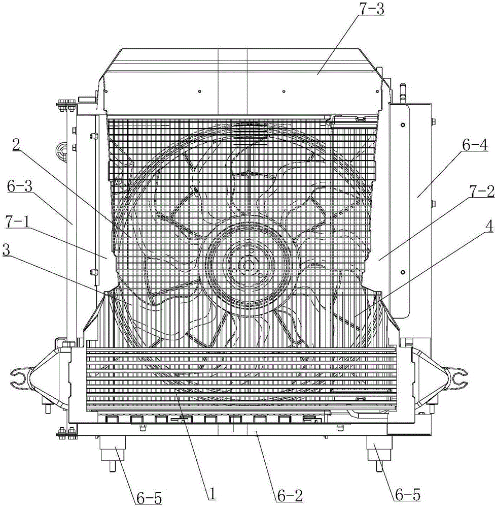
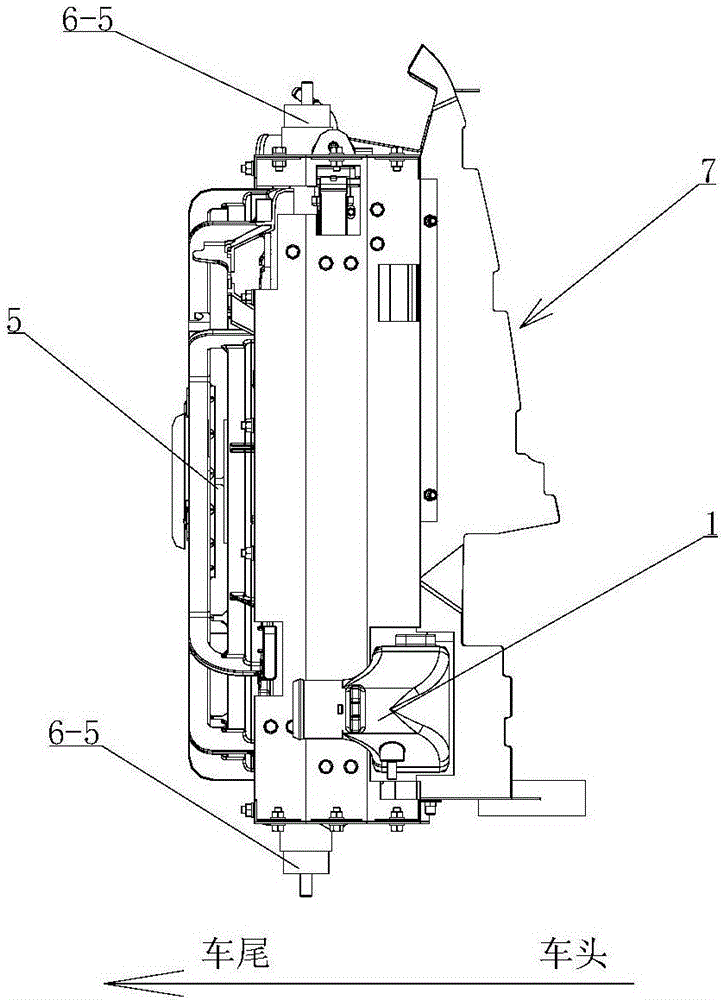
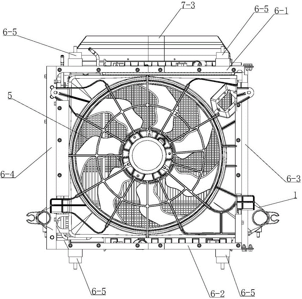
[0030] see Figure 1-8 , an integrated front-end cooling module for vehicles, including an intercooler 1, a condenser 2, a radiator 2, an oil cooler 4, a cooling fan 5, and a mounting frame 6. The installation frame is composed of an upper frame edge 6-1, a lower frame edge 6-2, a left frame edge 6-3 and a right frame edge 6-4, and a positioning frame is respectively arranged on the upper and lower frame edges near both ends. Column 6-5, the installation frame forms a connection with the surrounding sheet metal structure through four positioning columns. Along the direction from the front of the vehicle to the rear of the vehicle, the installation frame is divided into a front installation area, a middle installation area and a rear installa...


PUM


Abstract

An integrated front end cooling module for a vehicle comprises an intercooler, a condenser, a radiator, an oil cooler, a cooling fan and a mounting frame, wherein the mounting frame is connected with a surrounding metal plate structure through four positioning columns and is internally separated into a front mounting area, a middle mounting area and a rear mounting area, the condenser and the intercooler in vertical arrangement are mounted in the front mounting frame, the radiator and the oil cooler in parallel arrangement are mounted in the middle mounting area, the cooling fan is mounted in the rear mounting area, a air guiding unit comprising a left air guiding plate, a right air guiding plate and an upper air guiding plate is mounted at the front end of the mounting frame, and each of the air guiding plate is provided with a air guiding slope or a cambered air guiding surface used for guiding surrounding air into the mounting frame. The integrated front e3nd cooling module for the the vehicle has the advantages that air inlet quantity is increased, air is prevented from flowing out through gaps among the cooling units, mutual effects among the cooling units are reduced, and cooling efficiency of the cooling units is increased.

Description

technical field [0001] The invention belongs to the technical field of vehicle cooling, and in particular relates to an integrated front-end cooling module for vehicles. Background technique [0002] In the traditional vehicle cooling system, the common cooling components include the oil cooler for cooling the transmission oil, the intercooler for cooling the intake air of the turbocharged engine, the radiator for cooling the engine block, and the cooling system for the air conditioning system. Condenser for use and cooling fan for air suction, etc., where the cooling fan is used when the vehicle is idling or climbing at a low speed to suck in air to cool down the various cooling components. On existing vehicles, from the front of the vehicle to the rear of the vehicle, the layout of the cooling components is: oil cooler, condenser, radiator and fan, and the above cooling components are arranged sequentially from the front of the vehicle to the rear of the vehicle. The abov...

Claims


Application Information

Patent Timeline
IPC IPC(8): B60K11/04B60K11/06
CPCB60K11/04B60K11/06
Inventor 陈明陆新林李成史以奇
Owner TIANJIN SANDEN AUTO AIR CONDITIONING
Learn More